Electric motor car control apparatus

a technology for controlling apparatus and electric motors, applied in the direction of electric motor speed/torque regulation, battery/fuel cell control arrangement, transportation and packaging, etc., can solve the problems of inability to continue absorption, ineffective absorption of energy, limited capacity of power storage devices, etc., and achieve the effect of effective absorption of power

Inactive Publication Date: 2006-12-28
KK TOSHIBA
View PDF1 Cites 18 Cited by
  • Summary
  • Abstract
  • Description
  • Claims
  • Application Information

AI Technical Summary

Benefits of technology

[0010] In consideration of the above point, it is an object of the present invention to provide an electric motor car control apparatus which can effectively absorb power in a power storage device while keeping a balance between energy corresponding to a regeneration load shortage and absorbed energy.

Problems solved by technology

For this reason, absorbed energy becomes insufficient or excessive with respect to energy corresponding to a regeneration load shortage due to capacitor voltage detection errors and voltage differences, resulting in failure to effectively absorb energy.
Although control is performed to make an input current with a VVVF equal to an input current to the DC / DC converter or control is performed to make an input current to the overhead wire zero, it is difficult in this method to discriminate a load state on the overhead wire side, and regeneration energy which can be returned to the overhead wire side may be absorbed by the power storage device through the DC / DC converter.
Since the absorption capacity of the power storage device is limited, absorption cannot be continued.
In either of the above cases, the capacity of the VVVF power storage device cannot be used fully.
That is, absorption cannot be effectively performed.

Method used


Image

  • Electric motor car control apparatus
  • Electric motor car control apparatus
  • Electric motor car control apparatus

Examples


first embodiment

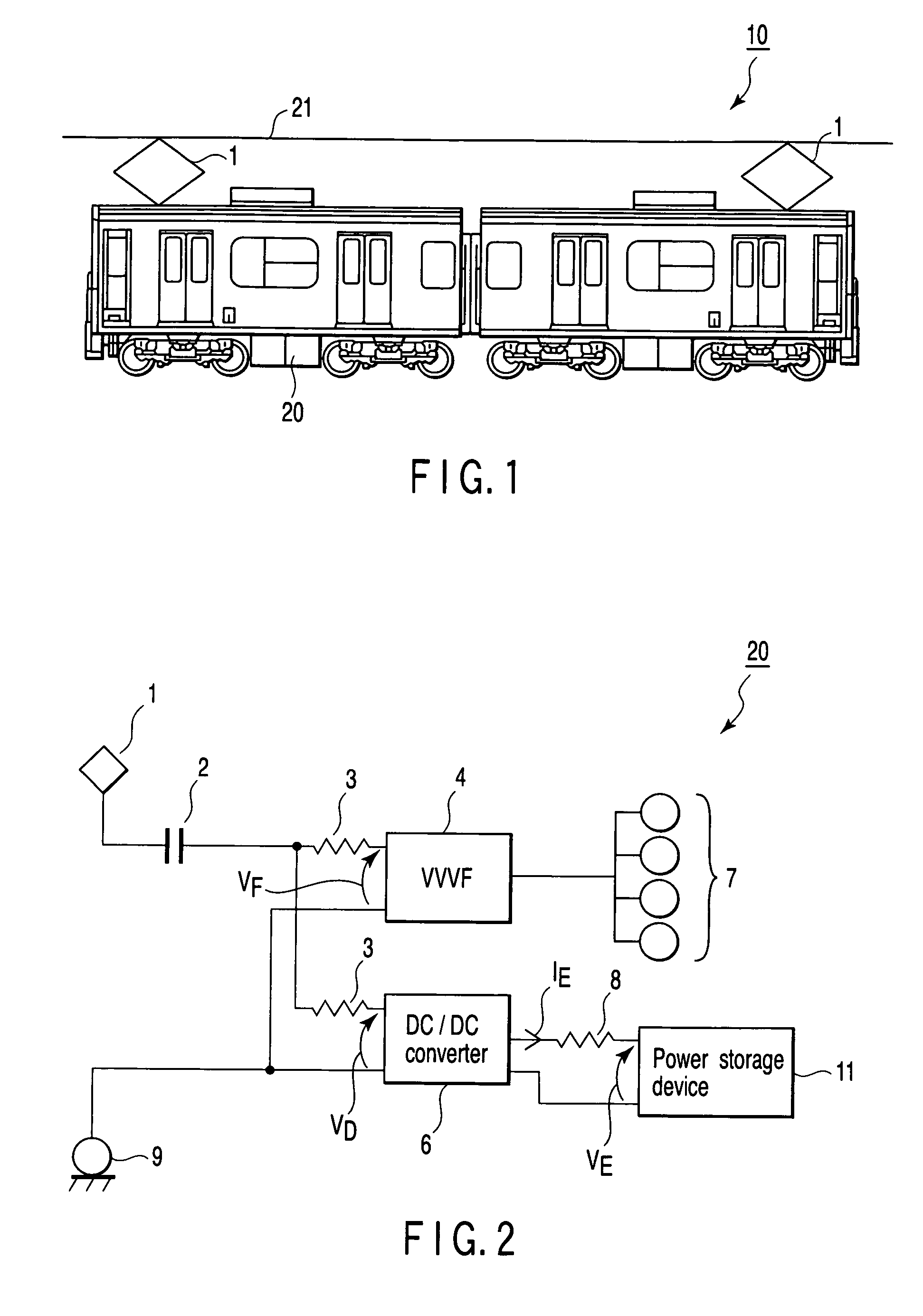
[0029]FIG. 1 is an external view showing an electric motor car comprising an electric motor car control apparatus according to a first embodiment of the present invention.

[0030] As shown in FIG. 1, an electric motor car 10 receives electricity from an overhead wire 21 through a pantograph1. The received electricity is input to an electric motor car control apparatus 20.

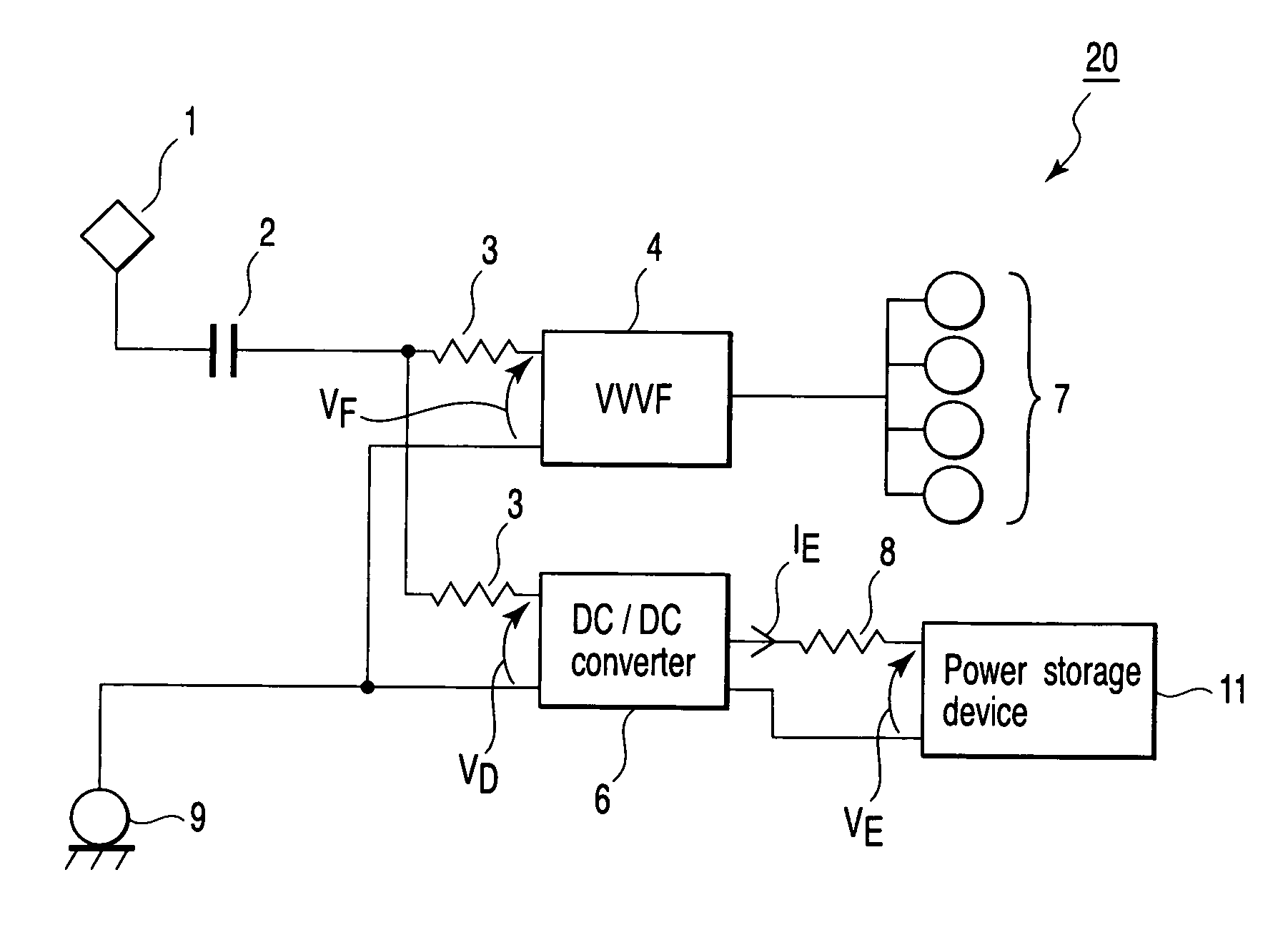
[0031]FIG. 2 is a block diagram showing the arrangement of the electric motor car control apparatus 20.

[0032] The electric motor car control apparatus 20 comprises the pantograph 1, a contactor 2, a filter reactor 3, a VVVF inverter 4, a DC / DC converter 6, a motor 7, a reactor 8, a wheel 9, and a power storage device 11. Let VF, VD, and VE be the voltages to be respectively applied to the VVVF inverter 4, DC / DC converter 6, and power storage device 11, and IE be the current flowing from the DC / DC converter 6 to the power storage device 11.

[0033] The operation of the electric motor car control apparatus 20 having t...

second embodiment

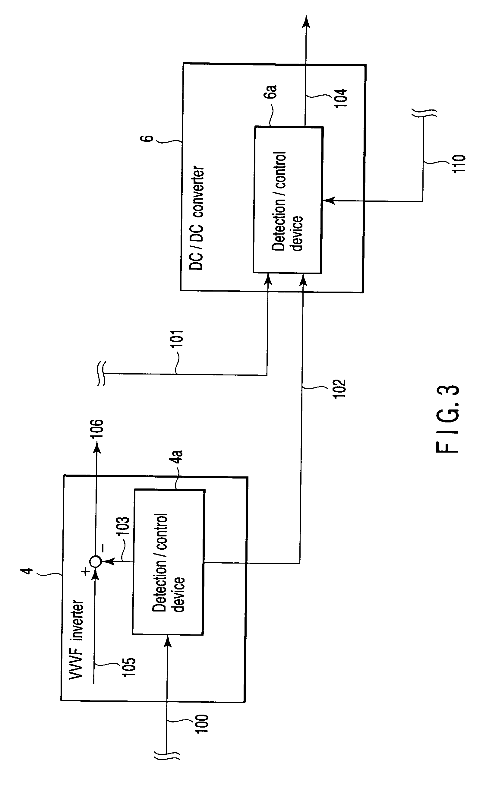
[0041] An electric motor car control apparatus according to a second embodiment of the present invention will be described next with reference to FIGS. 6 to 8. The same reference numbers as in the first embodiment denote the same parts in the second embodiment, and a detailed description thereof will be omitted.

[0042] The second embodiment differs from the first embodiment in that a detection / control device 4a of a VVVF inverter 4 outputs no information to a detection / control device 6a of a DC / DC converter 6, and an absorption start voltage value V3 of a DC / DC converter filter capacitor voltage value 101 with respect to a power storage device 11 is set in advance to be equal to an operation start voltage set value (regeneration limiter start voltage value) V1 of a filter capacitor voltage value 100.

[0043]FIG. 7 shows the relationship between a regeneration brake choke amount α and the operation start voltage set value (regeneration limiter start voltage value) V1 of the filter cap...

third embodiment

[0046] An electric motor control apparatus according to a third embodiment of the present invention will be described next with reference to FIGS. 9 and 10. The same reference numbers as in the first embodiment denote the same parts in the third embodiment, and a detailed description thereof will be omitted.

[0047] The third embodiment differs from the first embodiment in that information output from a detection / control device 4a of a VVVF inverter 4 to a detection / control device 6a of a DC / DC converter 6 is different from regeneration brake choke amount information 103.

[0048] The DC / DC converter 6 further comprises a predetermined value detection unit 6b. The predetermined value detection unit 6b outputs a correction command for correcting an absorption start voltage value V3 to a value V3′ to the detection / control device 6a of the DC / DC converter 6 on the basis of the input regeneration brake choke amount information 103 (see FIG. 10). The predetermined value detection unit 6b is...


PUM


Abstract

An electric motor control apparatus including an inverter which drives a motor of an electric motor car, storage unit for storing energy for the motor, and a converter which is connected to the storage unit, the inverter comprising detection unit for detecting a power value of the motor, and transmission unit for transmitting the power value detected by the detection unit to the converter, and the converter comprising calculation unit for receiving the power value transmitted by the transmission unit, and calculating an absorption current on the basis of the received power value, and control unit for controlling the storage unit on the basis of the absorption current calculated by the calculation unit.

Description

CROSS-REFERENCE TO RELATED APPLICATIONS [0001] This application is based upon and claims the benefit of priority from prior Japanese Patent Application No. 2005-136670, filed May 9, 2005, the entire contents of which are incorporated herein by reference. BACKGROUND OF THE INVENTION [0002] 1. Field of the Invention [0003] The present invention relates to an electric motor car control apparatus. [0004] 2. Description of the Related Art [0005] According to general techniques of electric double layer capacitor series connection in railway vehicles, as disclosed in, for example, Jpn. Pat. Appln. KOKAI Publication No. 2003-18702 and “A Study for Electric Double Layer Capacitor Series Connection for Railway Contraction”, 2003 JIASC Conference 3-32, so-called regeneration limiter control is performed in a technique using a VVVF inverter. Regeneration limiter control is performed as follows. When a VVVF inverter is set, during regeneration braking, in a light-load regeneration state in which...

Claims


Application Information

Patent Timeline
Patent Type & Authority Applications(United States)
IPC IPC(8): H02P27/04B60L7/24B60L9/18H02J7/00H02J7/14
CPCB60L9/16B60L11/1851B60L2200/26Y02T10/705Y02T10/7005B60L7/10B60L7/18B60L58/10Y02T10/70
Inventor TODA, SHINICHIMONDEN, YUKITAKA
Owner KK TOSHIBA
Why Eureka
Try Eureka