Optical device, and virtual image display

an optical device and virtual image technology, applied in the field of optical devices and virtual image displays, can solve the problems of large color and brightness unevenness, diffraction efficiency variation, and brightness unevenness, and achieve the effect of reducing color unevenness

Active Publication Date: 2006-12-28
SONY CORP
View PDF11 Cites 150 Cited by
  • Summary
  • Abstract
  • Description
  • Claims
  • Application Information

AI Technical Summary

Benefits of technology

[0051] In the optical device and virtual image display according to embodiments of the present invention, it is possible to reduce the unevenness of color and brightness due to angles of view by forming the angle formed between the interference fringes and hologram surfaces of at least the second reflection-type volume hologram grating at the incident side for the incident main light beams to meet the Bragg condition.

Problems solved by technology

However, the virtual image display 100 has incurred large unevenness of color and brightness in the past.
Also, in case the wavelength of light incident upon the hologram is short, the diffraction efficiency will possibly vary depending upon an angle of view and brightness will possibly be uneven.

Method used


Image

  • Optical device, and virtual image display
  • Optical device, and virtual image display
  • Optical device, and virtual image display

Examples


Embodiment Construction

[0066] The present invention will be described in detail below concerning an optical device and virtual image display as embodiments thereof with reference to the accompanying drawings.

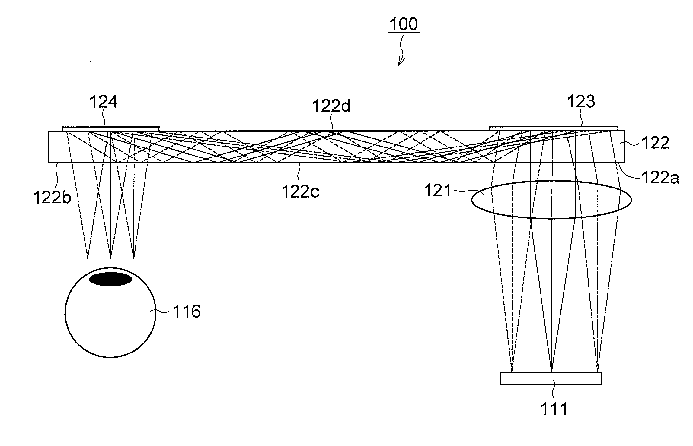
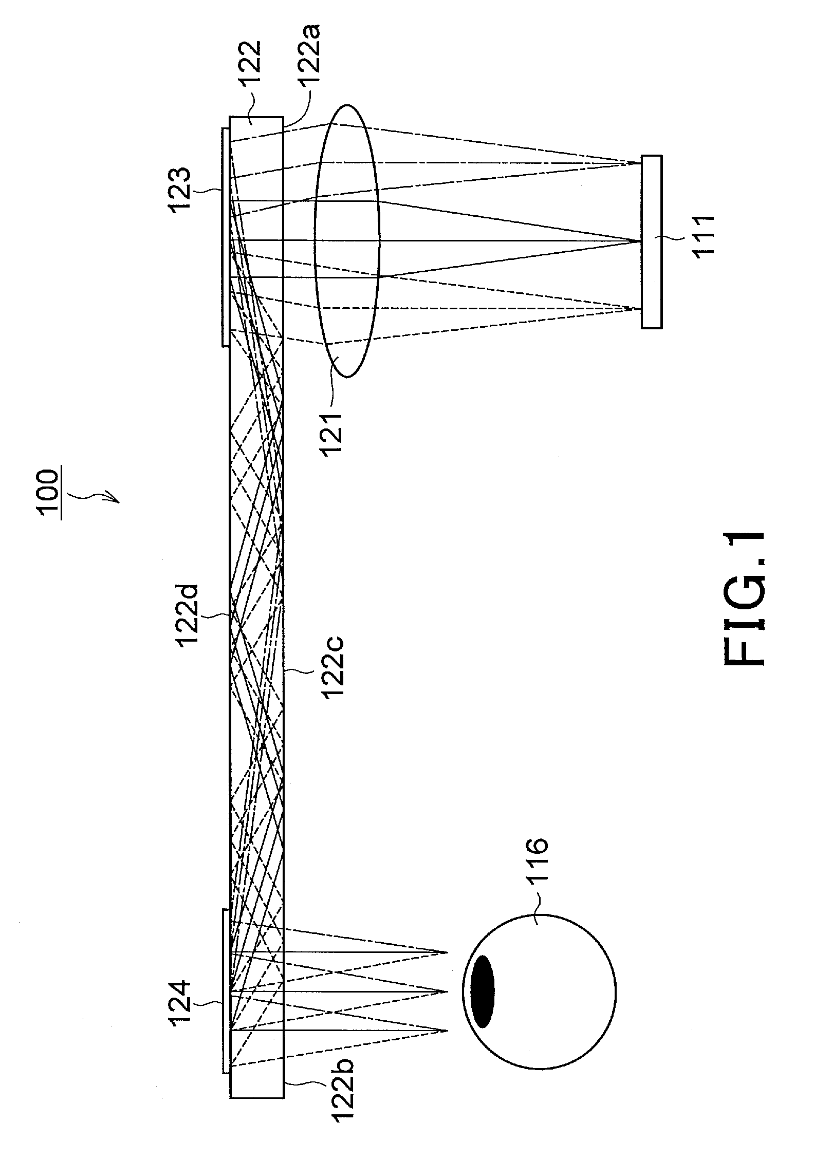
[0067] Referring now to FIG. 5, there is illustrated in the form of a schematic sectional view the optical device as the embodiment of the present invention. As shown, the optical device, generally indicated with a reference numeral 10, includes an illumination light source 11 to emit illumination light, spatial modulation element 12 to make spatial modulation of the illumination light coming from the illumination light source 11, and a virtual image optical system to receive the illumination light having been subjected to the spatial modulation in the spatial modulation element 12 and guide the light to the viewer's pupil 16.

[0068] Between the illumination light source 11 and spatial modulation element 12, there are provided a light pipe 13 to transmit the illumination light emitted from the illumi...


PUM


Abstract

There is provided an optical device including an optical waveguide upon which a group of parallel light beams different in traveling direction from each other are incident and from which the group of parallel light beams go out after propagated by repeated total reflection through it. The optical waveguide includes a first reflection-type volume hologram grating, and a second reflection-type volume hologram grating. The pitches of interference fringes on the hologram surfaces of the first and second reflection-type volume hologram gratings are equal to each other. In at least the second reflection-type volume hologram grating, the angle formed between the interference fringes and hologram surfaces are varied continuously or stepwise within the hologram in relation to the main incident light beam so as to meet the Bragg condition. Therefore, it is possible to reduce the unevenness of color and brightness due to angles of view.

Description

CROSS REFERENCES TO RELATED APPLICATIONS [0001] The present invention contains subject matter related to Japanese Patent Application JP 2005-178376 filed in the Japanese Patent Office on June 17, 2005, the entire content of which is incorporated herein by reference. BACKGROUND OF THE INVENTION [0002] 1. Field of the Invention [0003] The present invention relates to a thin-type optical device that guides display-image light to a viewer's pupil, and a virtual image display including the optical device and that displays a two-dimensional image as a virtual image enlarged by a virtual image optical system to the viewer. [0004] 2. Description of the Related Art [0005] To display a two-dimensional image as a virtual image enlarged by a virtual image optical system to the viewer, there is well known a virtual image display, generally indicated with a reference numeral 100, as shown in FIG. 1. This virtual image display 100 uses a reflection-type volume hologram grating selected from among ...

Claims


Application Information

Patent Timeline
Patent Type & Authority Applications(United States)
IPC IPC(8): G02B5/32
CPCG02B5/32G02B6/00G02B6/0035G02B27/0025G02B2027/0118G02B27/0103G02B27/0927G02B27/0944G02B2027/0112G02B27/0081G02B27/02G02B5/18
Inventor MUKAWA, HIROSHI
Owner SONY CORP
Why Eureka
Try Eureka