Susceptor for heat treatment and heat treatment apparatus

a technology of heat treatment apparatus and susceptor, which is applied in the direction of drying machines, drying, light and heating apparatus, etc., can solve the problems of high probability of cracking in semiconductor wafers, affecting the formation of good devices, and affecting the effect of heat treatment effect, so as to prevent cracking in substrates

Inactive Publication Date: 2006-12-28
DAINIPPON SCREEN MTG CO LTD
View PDF4 Cites 77 Cited by
  • Summary
  • Abstract
  • Description
  • Claims
  • Application Information

AI Technical Summary

Benefits of technology

[0011] The substrate is held in the recessed portion having the concave configuration greater in plan view size than the substrate as seen in plan view. As a result, a gap filled with a layer of gas is formed between the upper surface of the heat treatment susceptor and the lower surface of the substrate, to prevent a crack in the substrate when the substrate is exposed to a flash of light from the at least one flash lamp.
[0013] This allows the formation of the concave configuration relatively easily.
[0016] A gap filled with a layer of gas is formed between the upper surface of the heat treatment susceptor and the lower surface of the substrate, to prevent a crack in the substrate when the substrate is exposed to a flash of light from the at least one flash lamp.
[0017] It is therefore an object of the present invention to provide a heat treatment susceptor and a heat treatment apparatus which are capable of preventing a crack in a substrate when the substrate is exposed to a flash of light from a flash lamp.

Problems solved by technology

The occurrence of such a phenomenon causes the depth of the junction to exceed a required level, giving rise to an apprehension about a hindrance to good device formation.
A heat treatment apparatus employing such a xenon flash lamp, which momentarily exposes the semiconductor wafer to light having ultrahigh energy, rapidly raises the surface temperature of the semiconductor wafer for a very short period of time, to cause the abrupt thermal expansion of the wafer surface, resulting in a high probability that a crack occurs in the semiconductor wafer.
The cracks, however, still occur with considerable frequency, depending on the types of semiconductor wafers and heat treatment conditions (preheating temperature, energy of light for exposure, and the like).

Method used


Image

  • Susceptor for heat treatment and heat treatment apparatus
  • Susceptor for heat treatment and heat treatment apparatus
  • Susceptor for heat treatment and heat treatment apparatus

Examples


Embodiment Construction

[0028] A preferred embodiment according to the present invention will now be described in detail with reference to the drawings.

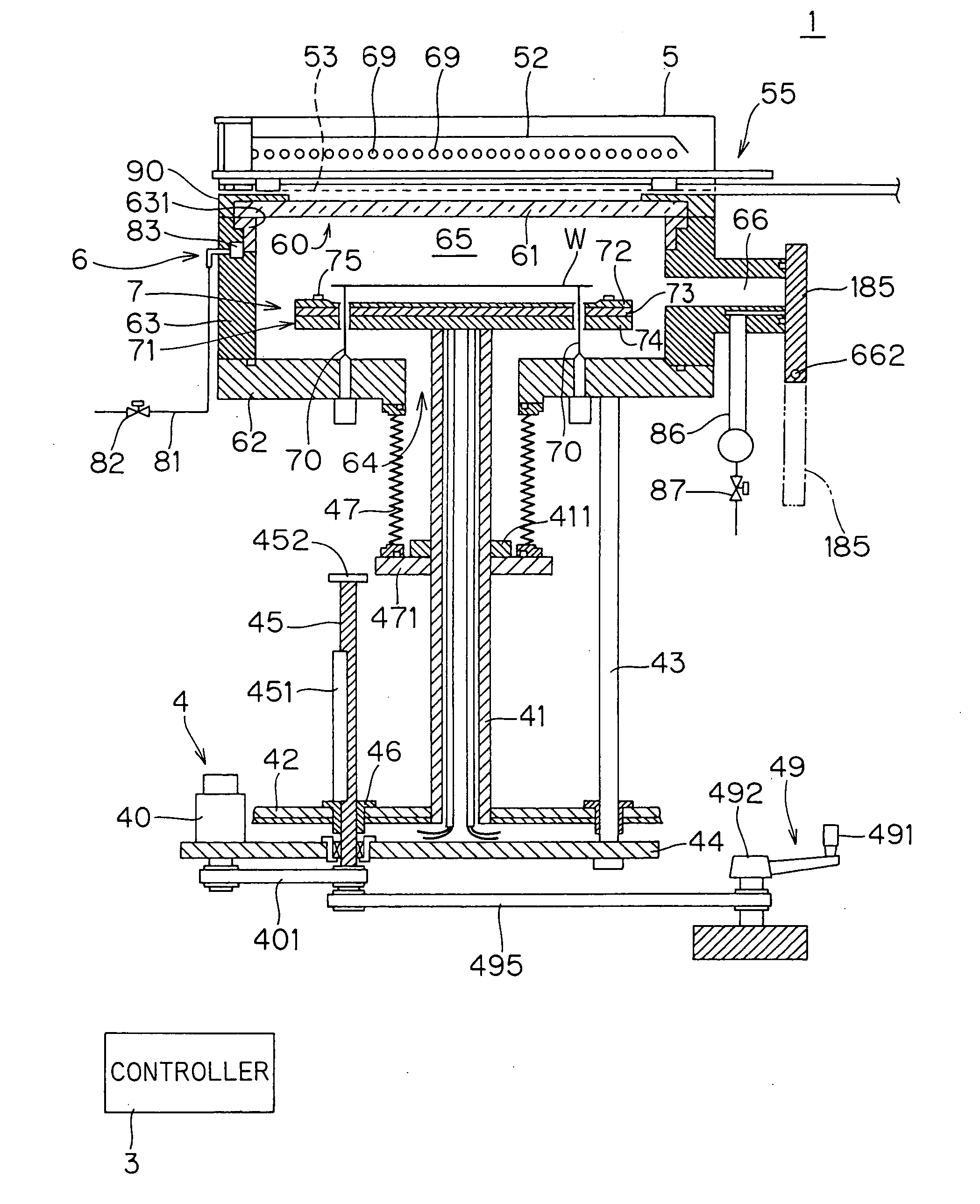
[0029] First, the overall construction of a heat treatment apparatus according to the present invention will be outlined. FIG. 1 is a side sectional view showing the construction of a heat treatment apparatus 1 according to the present invention. The heat treatment apparatus 1 is a flash lamp annealer for exposing a circular semiconductor wafer W serving as a substrate to a flash of light to heat the semiconductor wafer W.

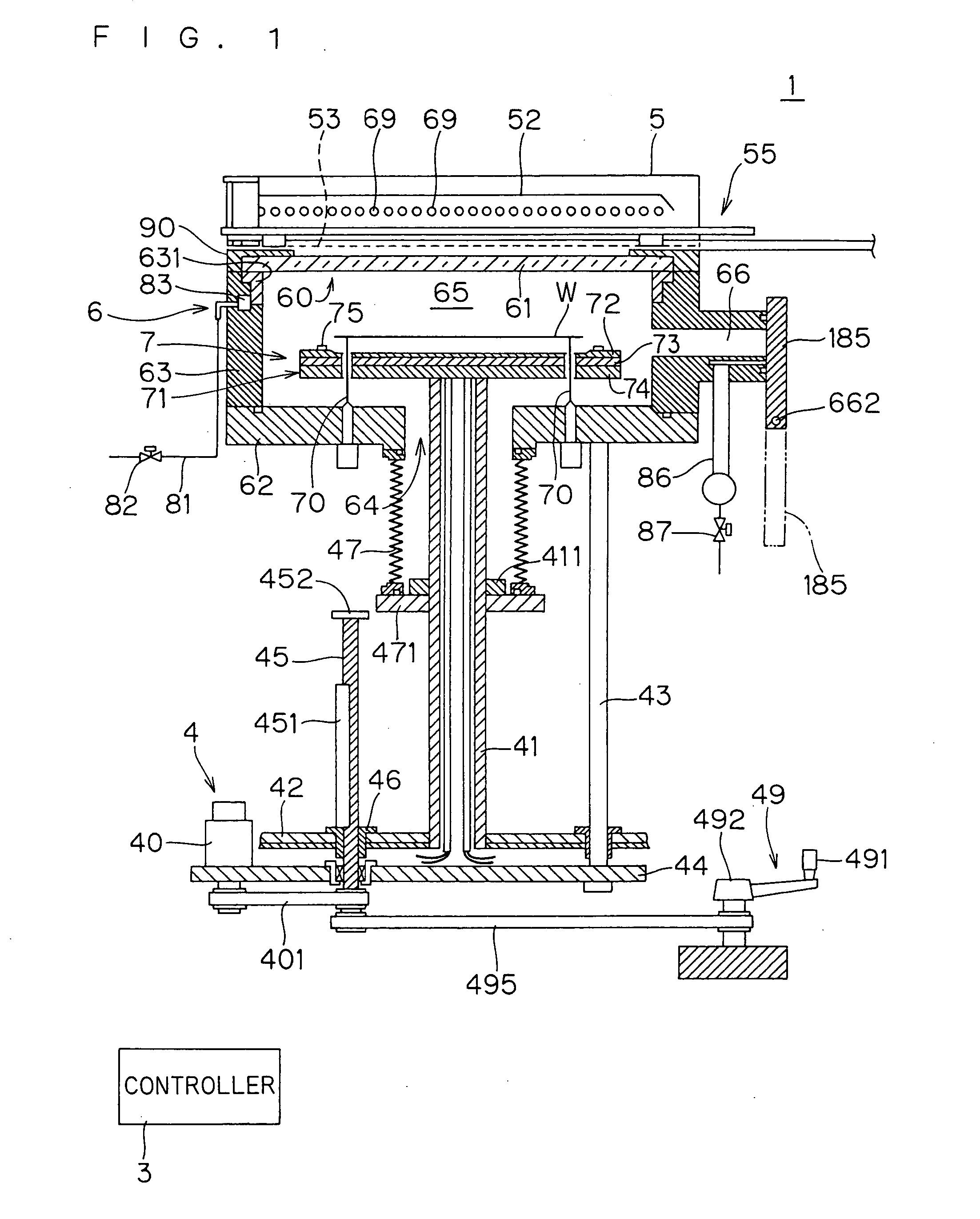
[0030] The heat treatment apparatus 1 comprises a chamber 6 of a generally cylindrical configuration for receiving a semiconductor wafer W therein. The chamber 6 includes a chamber side portion 63 having an inner wall of a generally cylindrical configuration, and a chamber bottom portion 62 for covering a bottom portion of the chamber side portion 63. A space surrounded by the chamber side portion 63 and the chamber bottom portion 62 is ...


PUM


Abstract

A susceptor for holding a semiconductor wafer when flash heating is performed by exposing the semiconductor wafer to a flash of light from flash lamps is formed with a recessed portion of a concave configuration having an outer diameter greater than the diameter of the semiconductor wafer, as seen in plan view. When the susceptor is viewed from above, the concave configuration of the recessed portion is greater in plan view size than the semiconductor wafer. The susceptor formed with the recessed portion holds the semiconductor wafer in such a manner that an inner wall surface of the recessed portion supports a peripheral portion of the semiconductor wafer. As a result, a gap filled with a layer of gas is formed between the lower surface of the semiconductor wafer and the upper surface of the susceptor, to prevent a crack in the semiconductor wafer when the semiconductor wafer is exposed to a flash of light from the flash lamps.

Description

BACKGROUND OF THE INVENTION [0001] 1. Field of the Invention [0002] The present invention relates to a heat treatment susceptor for holding a substrate including a semiconductor wafer, a glass substrate for a liquid crystal display device and the like which is to be heat-treated during the heat treatment thereof, and a heat treatment apparatus including the heat treatment susceptor. [0003] 2. Description of the Background Art [0004] Conventionally, a lamp annealer employing a halogen lamp has been typically used in the step of activating ions in a semiconductor wafer after ion implantation. Such a lamp annealer carries out the activation of ions in the semiconductor wafer by heating (or annealing) the semiconductor wafer to a temperature of, for example, about 1000° C. to about 1100° C. Such a heat treatment apparatus utilizes the energy of light emitted from the halogen lamp to raise the temperature of a substrate at a rate of about hundreds of degrees per second. [0005] In recent ...

Claims


Application Information

Patent Timeline
Patent Type & Authority Applications(United States)
IPC IPC(8): A21B2/00
CPCH01L21/68735H01L21/67115
Inventor NOZAKI, YOSHIHIDENISHIHARA, HIDEOKIYAMA, HIROKI
Owner DAINIPPON SCREEN MTG CO LTD
Why Eureka
Try Eureka