Sealed prismatic battery

a prismatic battery and seal technology, applied in the direction of vent arrangement, cell components, cell component details, etc., can solve the problems of abnormal rise in battery internal pressure, and contents scattering, so as to achieve stable opening pressure on the safety vent 16 and less deformation

Inactive Publication Date: 2006-12-28
HITACHT MAXELL LTD
View PDF1 Cites 26 Cited by
  • Summary
  • Abstract
  • Description
  • Claims
  • Application Information

AI Technical Summary

Benefits of technology

[0005] An object of the present invention is to provide a sealed prismatic battery in which the opening pressure of the safety vent is stable even if the bottom wall of the looped groove of the safety vent varies in thickness in each battery during the course of mass production. It is to be note that the safety vent can be referred to as a break vent.
[0013] That is, according to the safety vent 16 of the present invention, the end side groove portion 22 deforms less easily by the large thickness of the bottom wall of the end side groove portion 22 as described above, and the safety vent 16 operates effectively reliably when the battery internal pressure abnormally rises. Therefore, even if the thickness of the bottom wall of the looped groove 19 is varied by a manufacturing error, a stable opening pressure on the safety vent 16 can be obtained. Moreover, even if the battery internal pressure is not so high when the battery internal pressure abnormally rises, the safety vent 16 can reliably be broken. Since the end side groove portion 22 is formed linearly extending in the depthwise direction, an improved opening property of the safety vent 16 is obtained also from the viewpoint.
[0014] When the looped groove 19 is provided in the region where the recess 17 is formed, the bottom wall of a small thickness of the looped groove 19 can be easily reliably subjected to press working. Also, with this arrangement, the variation in the thickness of the bottom wall of the looped groove 19 can be reduced, and a more stable opening pressure of the safety vent 16 can be obtained.
[0015] By the front and rear groove portions 20 and 21 of the looped groove 19 being formed linearly extending parallel in the lateral direction, the bottom walls of the front and rear groove portions 20 and 21 can easily be torn off with the tongue portion 25.

Problems solved by technology

In the sealed prismatic battery, a short circuit state occurs in the battery to generate a gas, and the battery internal pressure abnormally rises when an excessive electrical load is applied or an excessive thermal load is applied.
Also, when the battery is excessively electrically charged, a gas is generated in the battery due to the decomposition of the electrolyte, and the battery internal pressure abnormally rises.
When the battery becomes unable to endure the abnormal rise in the internal pressure, the battery ruptures and the contents scatter.
The looped groove of the safety vent in the above prior art is formed on the cap by press working, and therefore, it is difficult to uniform the thickness of the bottom wall of the looped groove of each battery during battery mass production.
Therefore, a problem resides in that the opening pressure of the safety vent disadvantageously varies in each battery, lowering the reliability of the safety vent.

Method used


Image

  • Sealed prismatic battery
  • Sealed prismatic battery
  • Sealed prismatic battery

Examples


embodiment 1

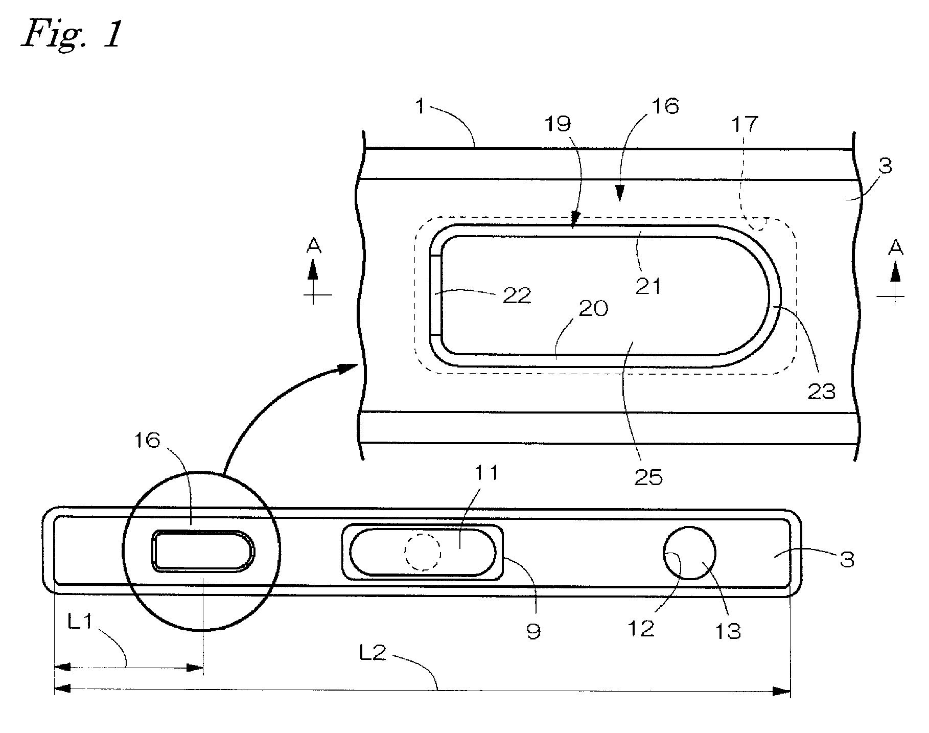
[0024]FIGS. 1 through 4 show a lithium ion secondary battery of Embodiment 1 as the sealed prismatic battery of the present invention. As shown in FIG. 4, the battery has a closed bottom prismatic tube-shaped battery can 1 that has a laterally elongated opening on its upper surface, an electrode body 2 and a nonaqueous electrolyte housing in the battery can 1, a laterally elongated cap 3 that closes the upper surface of the opening of the battery can 1, an insulator 5 made of a plastic material placed inside the cap 3 and so on. The battery can 1 was formed into a vertically elongated thin type by processing a plate material made of aluminum or its alloy by deep drawing with a width of 34 mm, a height of 50 mm and a thickness of 3.8 mm.

[0025] The electrode body 2 is formed by winding sheet-shaped positive and negative electrodes with interposition of a separator made of a microporous polyethylene film into a roll shape. A thin plate-shaped positive electrode current collection lead...

embodiment 2

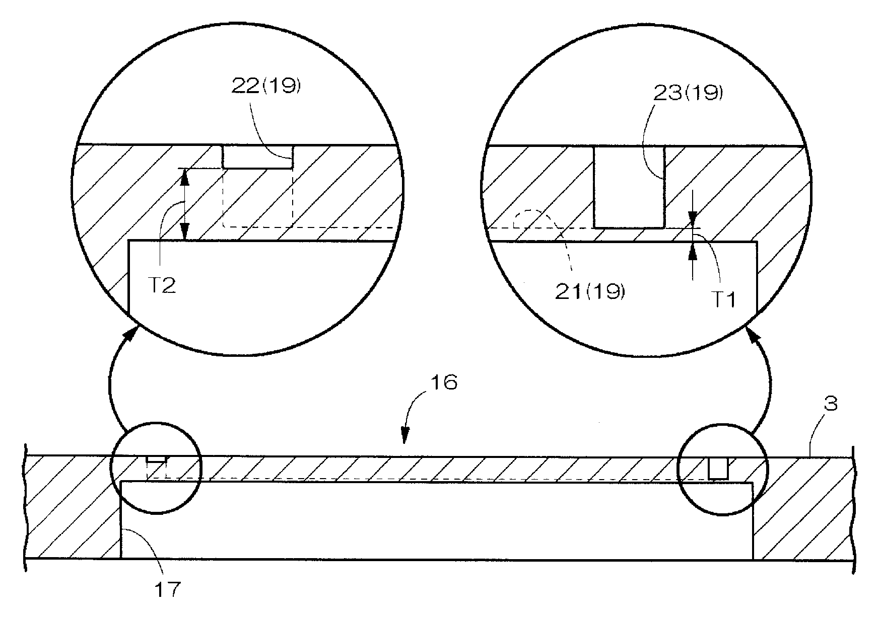
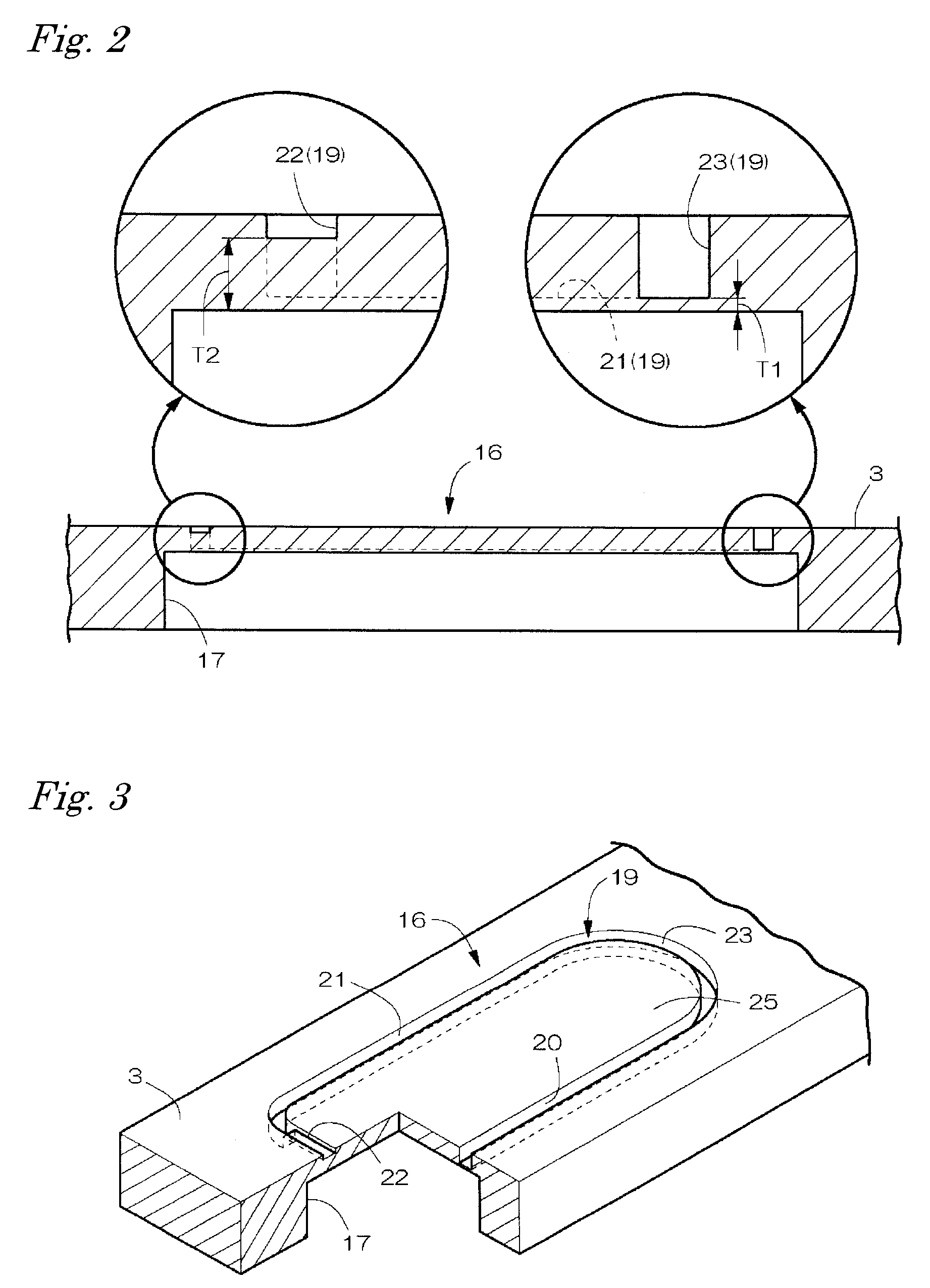
[0037] In Embodiment 2, the thickness dimension T1 of each of the bottom walls of the groove portions 20, 21 and 23 other than the end side groove portion 22 was dimensionally set to 0.031 mm at the safety vent 16. Since other points are the same as those of Embodiment 1, no description is provided therefor.

embodiment 3

[0038] In Embodiment 3, the thickness of the battery was largely set to 4.0 mm, and the depthwise width dimension of the safety vent 16 was largely set to 2.5 mm in accordance with the enlargement of the thickness of the battery. The thickness dimension T1 of each of the bottom walls of the groove portions 20, 21 and 23 other than the end side groove portion 22 was dimensionally set to 0.035 mm. The other points were the same as those of Embodiment 1.


PUM

PropertyMeasurementUnit
thicknessaaaaaaaaaa
heightaaaaaaaaaa
widthaaaaaaaaaa

Abstract

A sealed prismatic battery includes a laterally elongated cap that closes the upper surface of the opening of a battery can 1 and a safety vent that is provided at the cap and opens when the battery internal pressure abnormally rises. The safety vent has a looped groove that is formed recessed and located nearer to the left end of the cap on the outer surface side of the cap. The looped groove is annularly formed of front, rear, left and right groove portions into a laterally elongated prismatic shape, and the thickness of the bottom wall of the end side groove portion is thicker than that of the bottom walls of the other groove portions. The center side groove portion of the looped groove is formed into a circular arc shape curved convex toward the center side of the cap.

Description

BACKGROUND OF THE INVENTION [0001] The present invention relates to a sealed prismatic battery that has a safety vent which opens when a battery internal pressure abnormally rises. [0002] In the sealed prismatic battery, a short circuit state occurs in the battery to generate a gas, and the battery internal pressure abnormally rises when an excessive electrical load is applied or an excessive thermal load is applied. Also, when the battery is excessively electrically charged, a gas is generated in the battery due to the decomposition of the electrolyte, and the battery internal pressure abnormally rises. When the battery becomes unable to endure the abnormal rise in the internal pressure, the battery ruptures and the contents scatter. Therefore, the battery has a safety vent that prevents the rupture of the battery in advance by releasing the battery internal pressure with open operation when the internal pressure becomes equal to or higher than a prescribed pressure. [0003] There a...

Claims


Application Information

Patent Timeline
Patent Type & Authority Applications(United States)
IPC IPC(8): H01M2/12H01M50/103H01M50/176H01M50/553H01M50/627
CPCH01M2/0207H01M2/06H01M2/361H01M2/30H01M2/1241Y02E60/10H01M50/3425H01M50/553H01M50/103H01M50/176H01M50/627H01M50/30H01M50/147H01M50/20
Inventor MATSUMOTO, YOSHIMIWATANABE, OSAMUSOMATOMO, YOSHIKI
Owner HITACHT MAXELL LTD
Why Eureka
Try Eureka