
Nidus position specifying system and radiation examination apparatus

Inactive Publication Date: 2006-12-28
KOJIMA SHINICHI +6
View PDF7 Cites 7 Cited by
  • Summary
  • Abstract
  • Description
  • Claims
  • Application Information

AI Technical Summary

Benefits of technology

"The present invention provides a system and method for accurately positioning a biological structure image in relation to a biological function image, even when the spatial resolution of the biological function image is deteriorated. The invention solves the problem of requiring a high-speed and high-function positional aligning operation by employing a method that can execute a positional aligning operation of images in a higher speed and with greater accuracy. The invention also allows for a simultaneous imaging operation of different modalities, such as X-ray CT and MRI, to be carried out with a single examination. The invention further provides a method for interpolating images to reduce image size and improve image quality. Overall, the invention improves the precision and efficiency of positional alignment in biological structure image analysis."

Problems solved by technology

However, this method owns the above-explained two problems.

Method used


Image

  • Nidus position specifying system and radiation examination apparatus
  • Nidus position specifying system and radiation examination apparatus
  • Nidus position specifying system and radiation examination apparatus

Examples


first embodiment

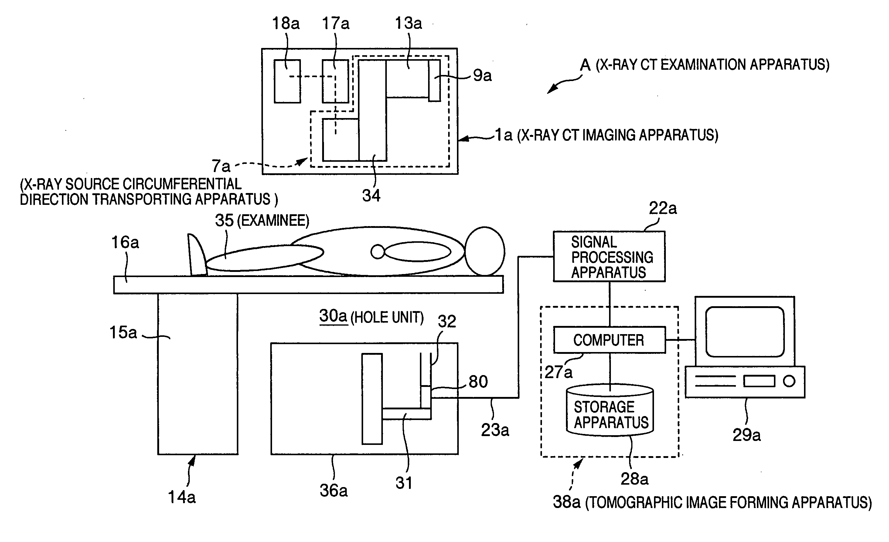
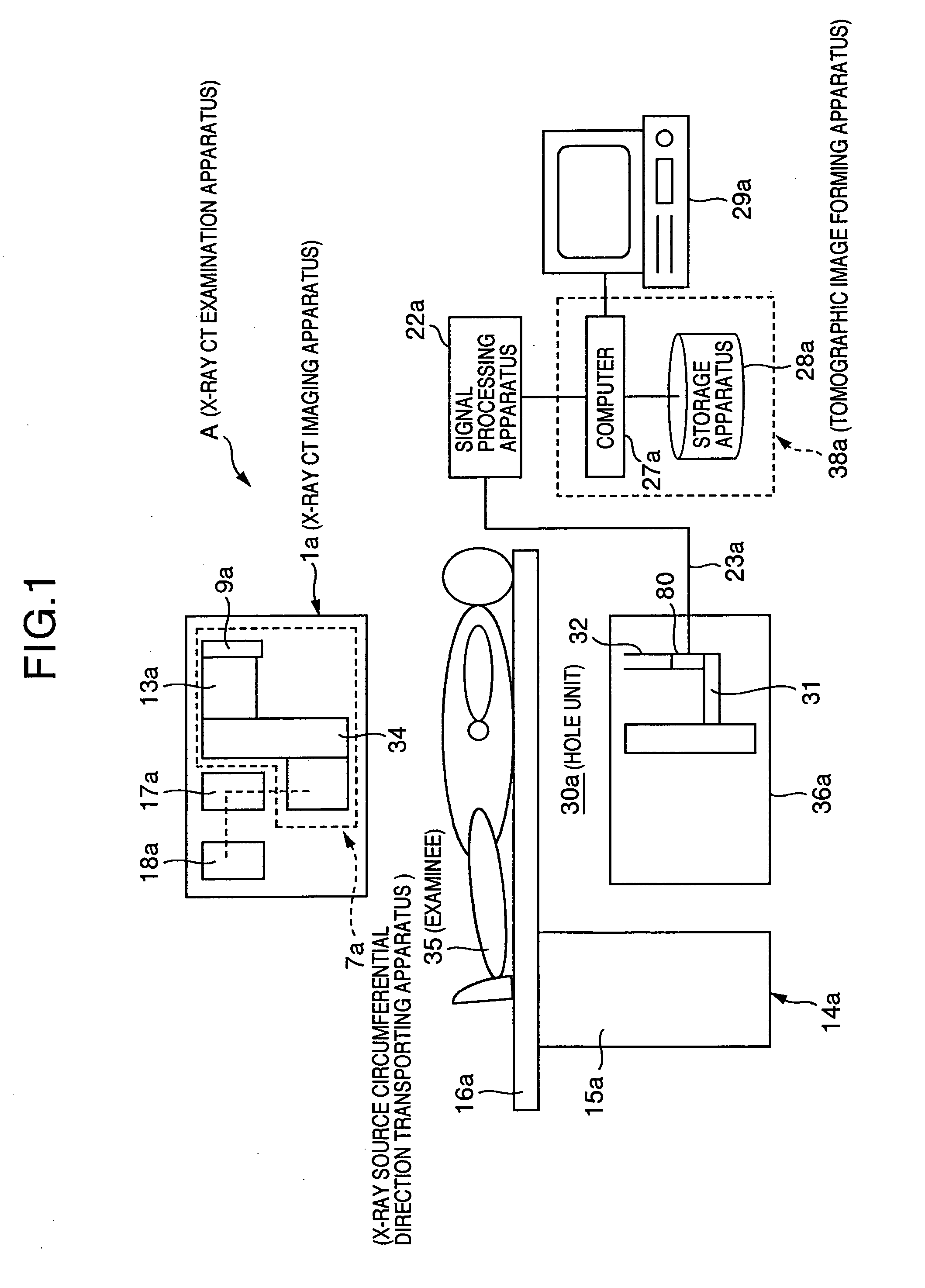
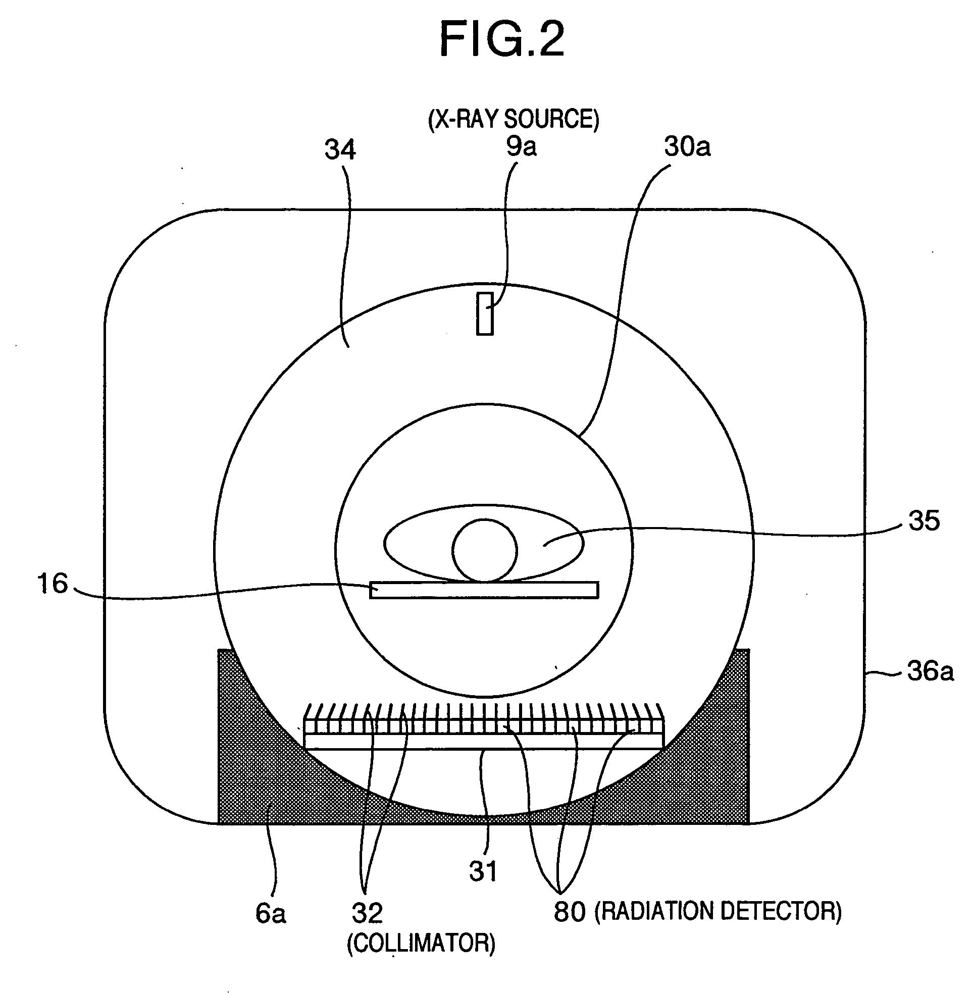
[0035] A first embodiment of the present invention will now be described with reference to FIG. 1 to FIG. 8. FIG. 1 is an X-ray CT examination apparatus, and FIG. 2 is a sectional view of the X-ray CT examination apparatus. FIG. 3 and FIG. 4 represent PET-X-ray CT examination apparatus.

[0036] In this first embodiment, a nidus position specifying system for specifying a nidus position of an examinee 35 is constituted by a PET-X-ray CT examination apparatus “B” (see FIG. 3) and an X-ray CT examination apparatus “A” (see FIG. 1). The PET-X-ray CT examination apparatus B corresponds to a biological function examination apparatus and a first biological structure examination apparatus. The X-ray CT examination apparatus A corresponds to a second biological structure examination apparatus.

[0037] First, as shown in FIG. 1, the X-ray CT examination apparatus A, according to this first embodiment, contains an X-ray CT imaging apparatus 1a, an examinee holding apparatus 14a, a tomographic im...

second embodiment

[0077] In the first embodiment, the simultaneous imaging operation capable apparatus (PET-X-ray CT examination apparatus B) of both the PET examination apparatus and the X-ray CT examination apparatus has been exemplified. Alternatively, if a positional relationship can be grasped, then simultaneous imaging operations are not necessarily required. To this end, a second embodiment of the present invention in such a case that both a PET examination apparatus and an X-ray CT examination apparatus are arrayed so as to acquire a positional relationship will now be described with reference to FIG. 9 to FIG. 11.

[0078] An imaging sequential operation of the second embodiment is not basically different from the imaging sequential operation shown in FIG. 8 of the first embodiment. Instead of the process operation defined in the step S52 of the first embodiment in which the imaging operations by the PET examination apparatus and the X-ray CT examination apparatus are carried out in the simult...

third embodiment

[0092] Although the positional alignments have been carried out in the images in the first and second embodiments, this third embodiment describes such a method for synthesizing sinogram data preceding to the above-explained images, and images in a frequency space. These positional alignments may become very effective in the case that there are different filters when image reconstructing operations of apparatus are carried out. This is because images themselves are different from each other in such a case that various sorts of filters are employed when an image reconstructing operation is carried out, and / or in such a case that different image reconstructing methods are employed. As a consequence, it is very important that a positional alignment is carried out by employing a sinogram. This third embodiment will be described as follows:

[0093]FIG. 12 is a flow chart for describing both an imaging operation and an image synthesizing operation, according to this third embodiment. First...


PUM


Abstract

An X-ray CT image of a low spatial resolution image is acquired by employing a PET-X-ray CT examination apparatus. Also, a PET image is acquired by employing the PET-X-ray CT examination apparatus. Furthermore, an X-ray CT image of a high spatial resolution image is acquired by employing another X-ray CT examination apparatus. Then, the X-ray CT image equal to the low spatial resolution image is corrected by employing the X-ray CT image, so that an X-ray CT image equal to a high spatial resolution image is obtained. Since a positional relationship of the resulting X-ray CT image with respect to the PET image can be grasped, this PET image can be simply synthesized with the X-ray CT image.

Description

[0001] This application is a continuation of application Ser. No. 10 / 912,166, filed Aug. 6, 2004, which is hereby incorporated by reference in its entirety.BACKGROUND OF THE INVENTION [0002] The present invention is related to a nidus position specifying system and a radiation examination apparatus with employment of an X-ray CT examination apparatus, a PET examination apparatus, a SPECT examination apparatus, and the like. [0003] As techniques capable of imaging biological functions and biological structures of interior portions of examinees in a non-invasive manner, there are examinations using radiation. X-ray CT, MRI, PET, SPECT examination apparatuses are available as a typical radiation examination apparatus. [0004] An X-ray CT (Computerized Tomography) imaging method corresponds to such a method that radiation emitted from an X-ray source is irradiated to an examinee, and a biological structure of an interior portion of this examinee is imaged based upon transmission of the r...

Claims


Application Information

Patent Timeline
Patent Type & Authority Applications(United States)
IPC IPC(8): A61B5/05A61B5/00G01R33/54A61B5/055A61B6/03G01R33/28G01T1/161G06T1/00G06T3/40G06T7/00
CPCA61B6/032A61B6/037A61B6/463A61B6/5235G06T2207/30004G06T7/0028G06T2207/10081G06T2207/10104G06T3/4007G06T7/33
Inventor KOJIMA, SHINICHIUENO, YUUICHIROUAMEMIYA, KENSUKEYANAGITA, NORIHITOKITAGUCHI, HIROSHITSUCHIYA, KATSUTOSHIYOKOI, KAZUMA
Owner KOJIMA SHINICHI
Learn More