
Thermal cautery surgical forceps

a technology of thermal cautery and forceps, which is applied in the field of hand-held, portable thermal cautery forceps, can solve the problems of heavy electrical components, bulky radio frequency surgical units, and heavy generators to operate, and achieve the effects of reducing cost, enhancing coagulation effectiveness, and facilitating grasping and direct coagulation

Inactive Publication Date: 2006-12-28
HERZON GARRETT D
View PDF51 Cites 17 Cited by
  • Summary
  • Abstract
  • Description
  • Claims
  • Application Information

AI Technical Summary

Benefits of technology

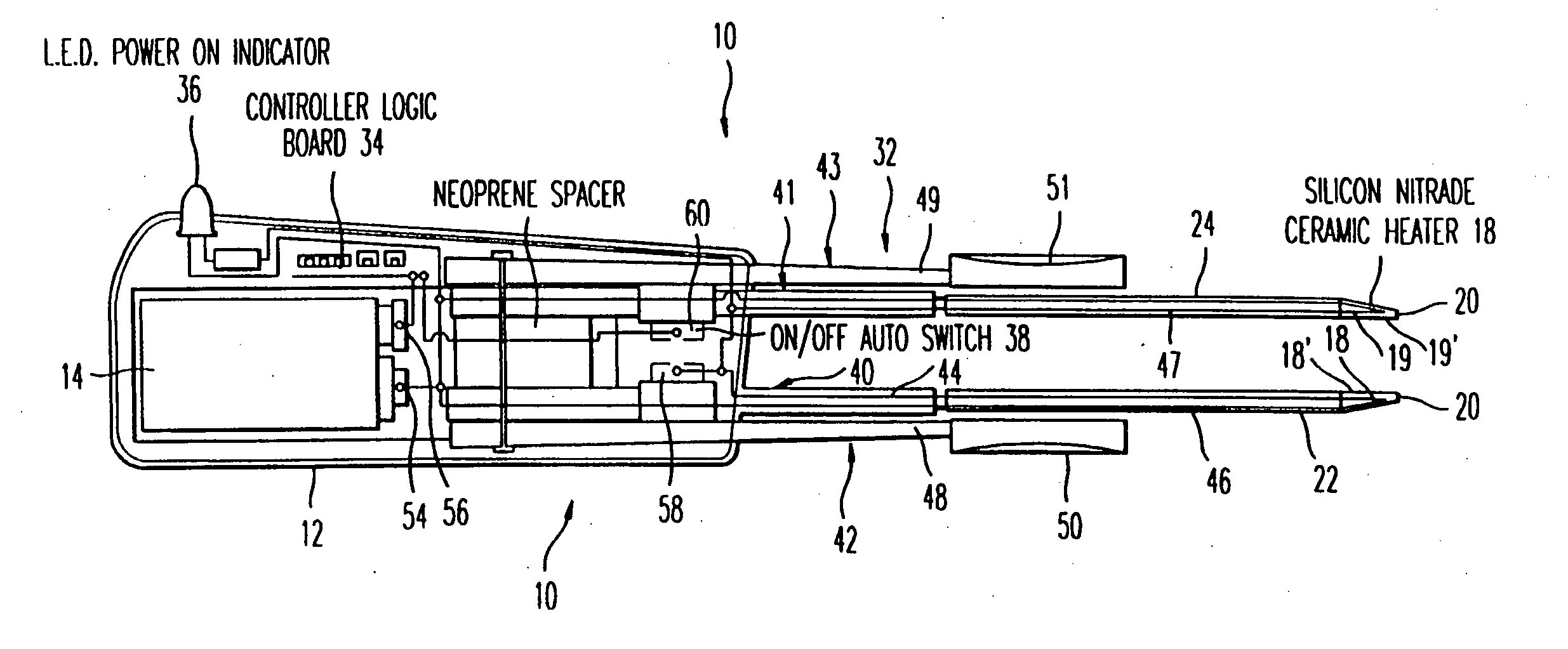
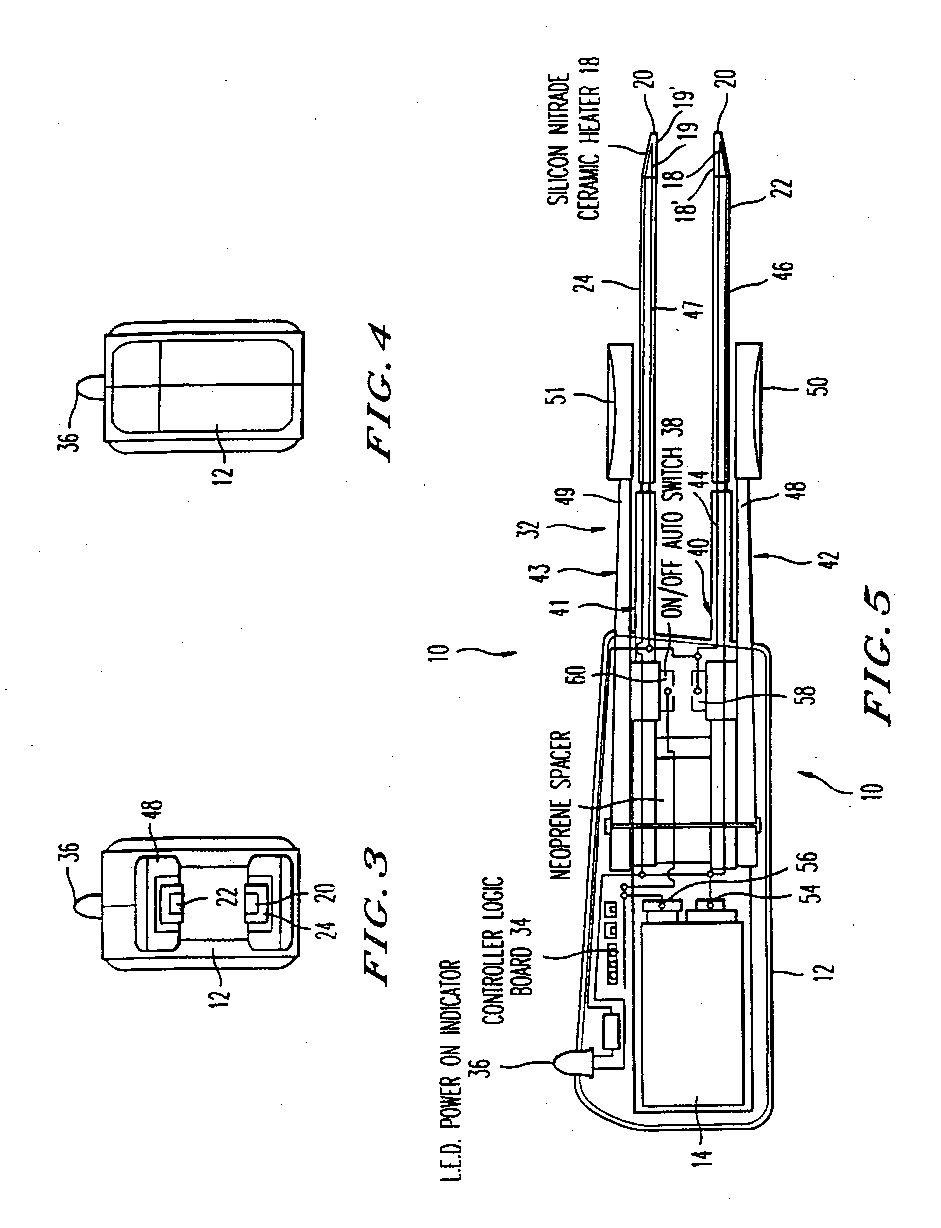
"The present invention provides a new and improved hand-held, high energy, portable thermal cautery forceps. The device is cordless and fully portable, with no need for cables or external power supply. It has a very high heating capacity, with temperatures over 1000°C easily obtainable. The thermal elements heat up quickly, within one second. The forceps can be used in emergency or field operations, as well as in clinics and surgery centers. The unique position of the ceramic heater elements allows for controlled coagulation of tissue and blood vessels. The device is packaged as a sterile disposable instrument, reducing cost and enhancing availability."

Problems solved by technology

This technique requires a bulky generator and heavy electrical components to operate.
More often than not, radio frequency surgical units are bulky expensive units which require a cable connection.
Employing RF cauterization in a surgical operation may add significant cost to the procedure because the grounding pad, cable and handpiece must all be either re-sterilized or replaced in the case of disposable use.
These devices have severe limitations as to their scope of use in surgery.
The heat generated by the handheld battery powered devices is very small with a low heat capacity.
These battery powered hot-wire cautery instruments are not effective for use in cauterization of larger blood vessels encountered in most surgical procedures.
This device is primarily for limited endoscopic applications.

Method used


Image

  • Thermal cautery surgical forceps
  • Thermal cautery surgical forceps
  • Thermal cautery surgical forceps

Examples


Embodiment Construction

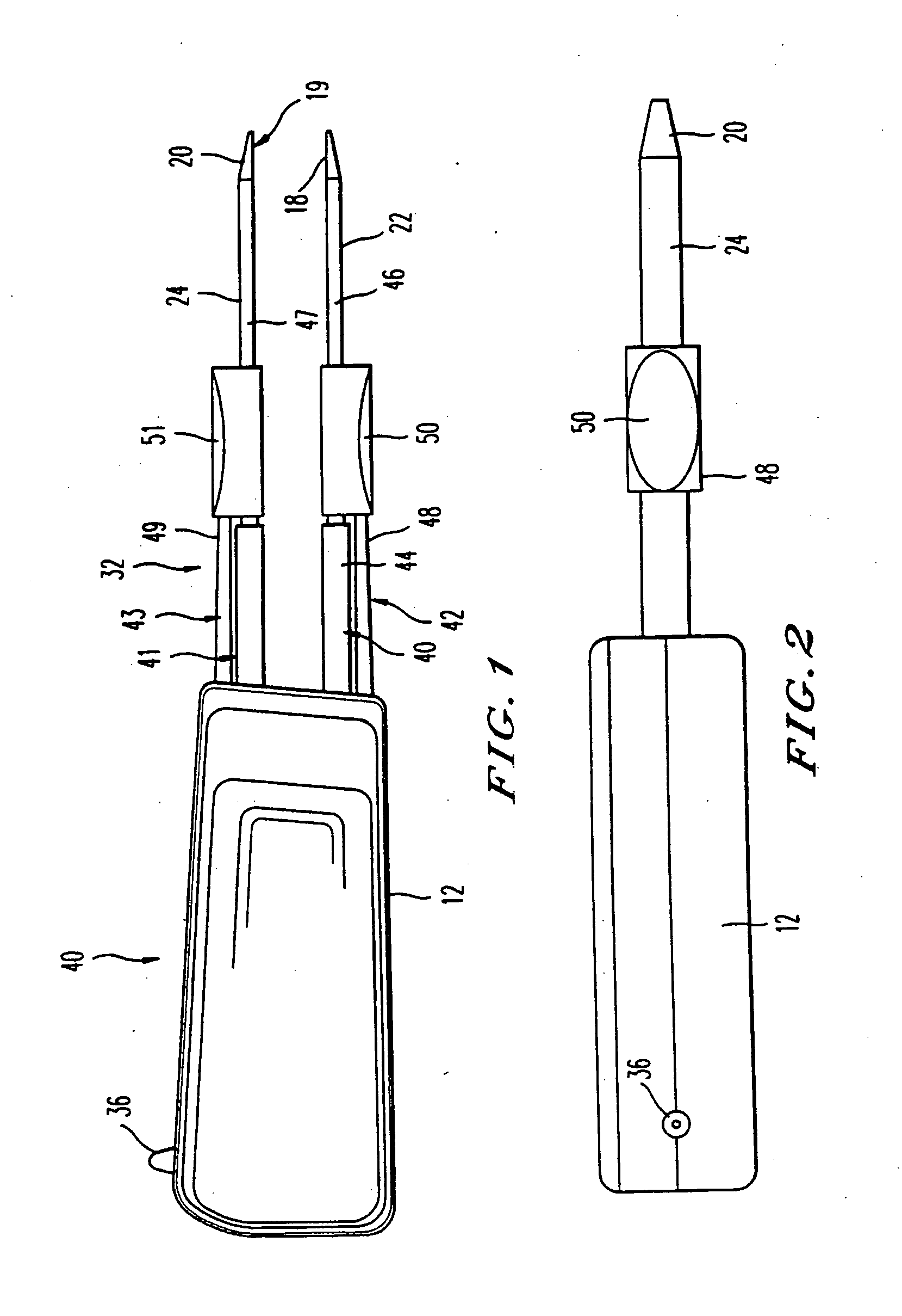
[0028] In accordance with a preferred embodiment of the invention, a new and improved thermocautery surgical forceps comprises a surgical forceps body including a pair of elongate tine members extending from the forceps body to respective free end tip portions spaced from the forceps body. The tine members are mounted to the forceps body in a manner providing resilient compressible movement of the tine members between a normally open position, wherein the tines are disposed in aligned, parallel, spaced-apart relationship, and a squeezed closed position, wherein the tip portions of the tine members are disposed in confronting abutting relationship. Each tine member includes a tissue contact surface defined on an inner facing surface of the tine member adjacent the tip portion. A ceramic heater element is disposed in each tine member so as to effectively heat the tissue contact surface to an elevated tissue cauterizing temperature. The ceramic heater elements are optionally connected ...


PUM


Abstract

A portable, thermal cauterizing forceps device for use in surgery. The device incorporates a pair of ceramic heater elements mounted within the tips of the tines of a forceps. The forceps is used to grasp tissue or blood vessels and apply heat to effect cauterization. In the case of the first embodiment of the invention, the forceps instrument incorporates a battery and control electronics. The thermal-forceps is of a self-contained wireless, handheld disposable design. In a second embodiment of the invention, the forceps handpiece is connected to an external power source. Both embodiments of the forceps incorporate set of rapidly heating ceramic heater elements that may be composed of silicon nitride. An LED provides the operator feedback as to the operating level of the heaters and / or battery reserve. Enhancements to the second embodiment include a rechargeable power supply, variable control of the heater temperature, as well as a, digital display of the tip temperature.

Description

[0001] This application is a continuation and claims the benefit of priority under 35 U.S.C. §120 from U.S. application Ser. No. 10 / 326,387, filed Dec. 23, 2002, which is a continuation of U.S. Pat. No. 6,533,778, issued Mar. 18, 2003, which is a continuation of U.S. Pat. No. 6,235,027, issued May 22, 2001.BACKGROUND OF THE INVENTION [0002] The present invention relates to a handheld, portable thermal-cauterizing forceps including an integrated thermal heating surface disposed at each tip. [0003] There are many surgical cautery devices available for the surgeon to ablate and vaporize tissue. Hot knives and cutting coagulators have been used to make skin incisions. The cautery can also be used in surgery to aid in hemostasis or control bleeding by coagulating blood vessels. Employing various cautery modalities decreases the duration of some surgical procedures by providing the surgeon a rapid method of coagulation without the need for suture ligation of blood vessels encountered duri...

Claims


Application Information

Patent Timeline
Patent Type & Authority Applications(United States)
IPC IPC(8): A61B18/04A61B17/00A61B18/08
CPCA61B18/085A61B18/08A61B18/04A61B2017/00734A61B18/10A61B2018/00404A61B2018/00595
Inventor HERZON, GARRETT D.
Owner HERZON GARRETT D
Learn More