Methods and systems for treating restenosis sites using electroporation
a technology of electroporation and restnosis, applied in the field of electroporation, can solve the problems of inability to closely monitor and control
- Summary
- Abstract
- Description
- Claims
- Application Information
AI Technical Summary
Benefits of technology
Problems solved by technology
Method used
Image
Examples
example 1
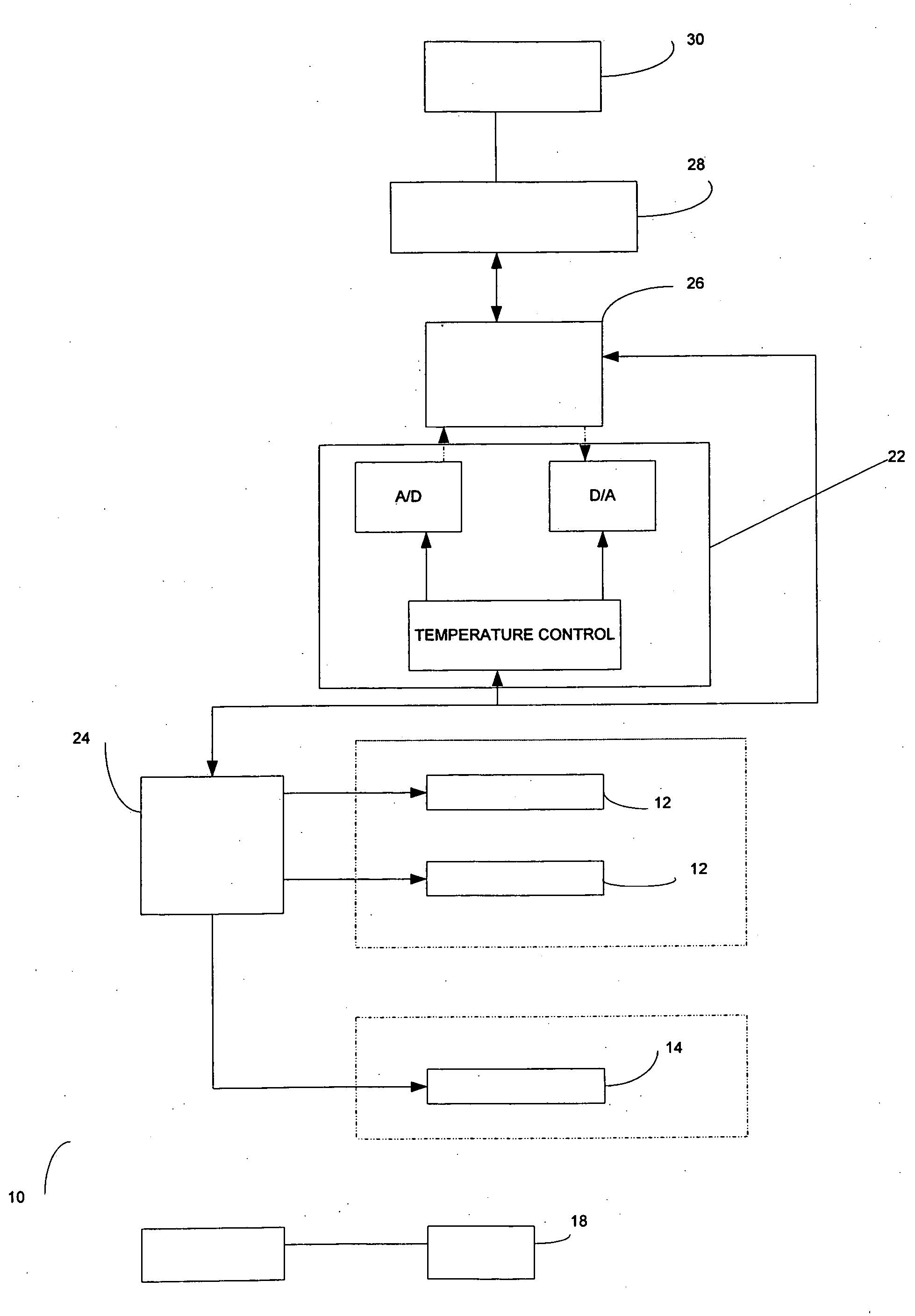
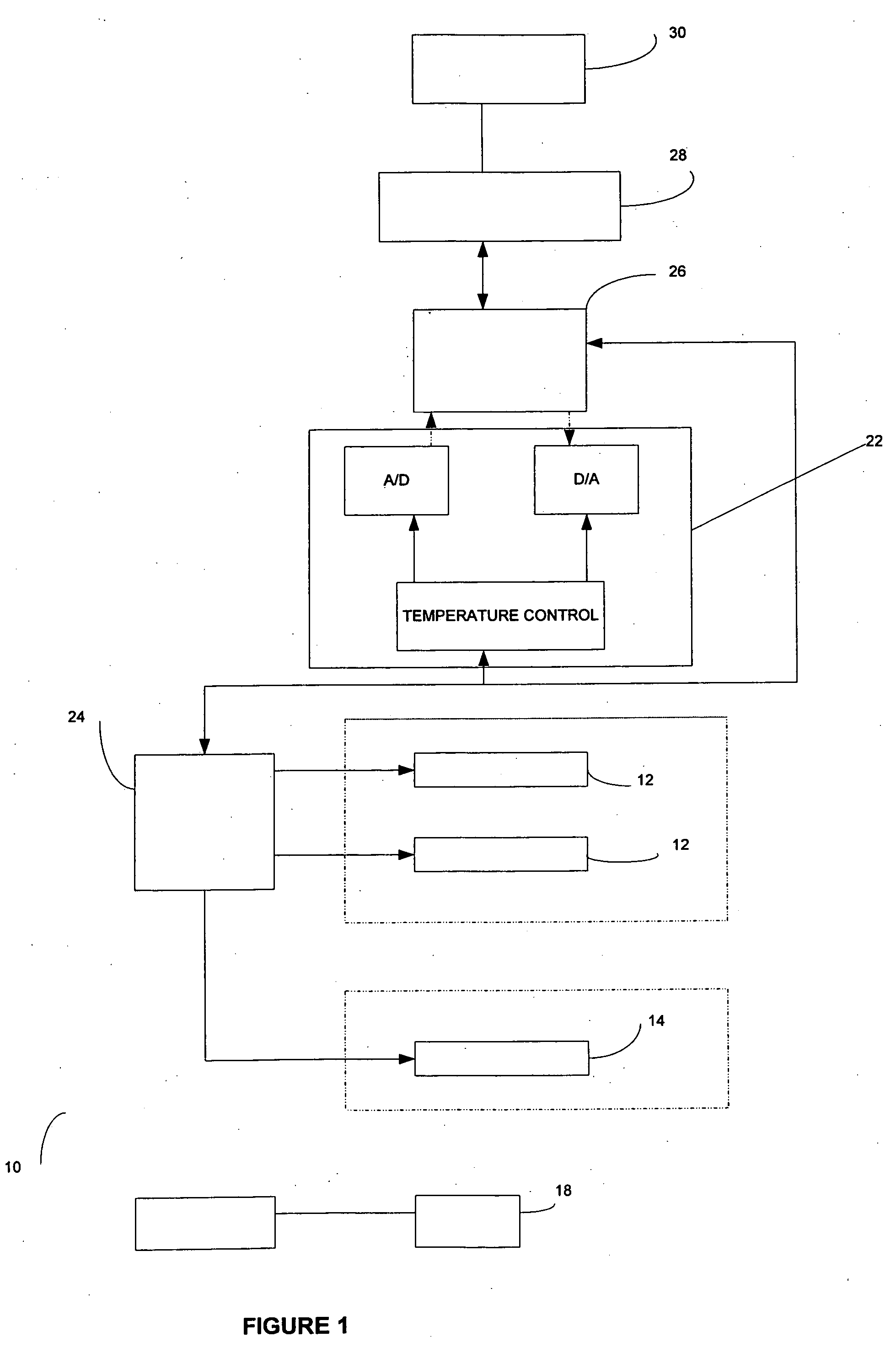
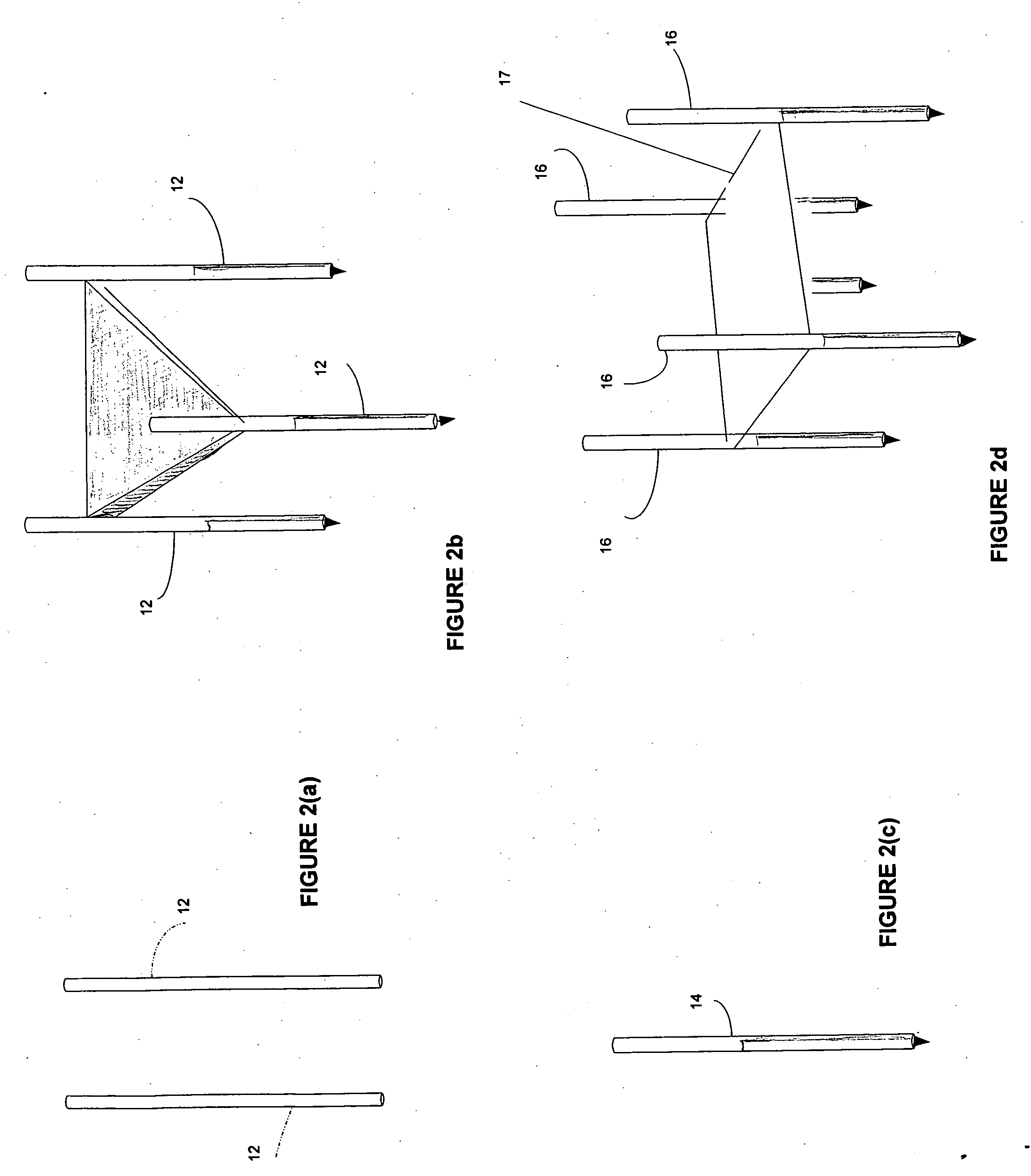
[0082] An area of the restenosis tissue site is imaged. A catheter 34, with the electroporation balloon 36 and two mono-polar electrodes 12, is introduced through the vasculature of a patient. The electroporation balloon 36 is positioned at the restenosis tissue site. Imaging is used to confirm that the mono-polar electrodes are properly placed. Pulses are applied with a duration of 5 microseconds to about 62 seconds each. Monitoring is preformed using ultrasound. The restenosis tissue site is monitored. In response to the monitoring, pulses are adjusted to maintain a temperature of no more than 100 degrees C. A voltage gradient at the restenosis tissue site in a range of from about 50 volt / cm to about 1000 volt / cm is created. A volume of the restenosis tissue site undergoes cell necrosis.
example 2
[0083] An area of the restenosis tissue site is imaged. A catheter 34, with the electroporation balloon 36 and a bipolar electrode 14 is introduced through the vasculature of a patient. The electroporation balloon 36 is positioned at the restenosis tissue site. Imaging is used to confirm that the electroporation balloon 36 is properly placed. Pulses are applied with a duration of about 90 to 110 microseconds each. Monitoring is performed using a CT scan. The restenosis tissue site is monitored. In response to the monitoring, pulses are adjusted to maintain a temperature of no more than 75 degrees C. A voltage gradient at the restenosis site in a range of from about 50 volt / cm to about 5000 volt / cm is created. A volume of the restenosis tissue site undergoes cell necrosis.
example 3
[0084] An area of the restenosis tissue site is imaged. A catheter 34, with the electroporation balloon 36 and a band 20 of mono-polar electrodes is introduced through the vasculature of a patient. The electroporation balloon 36 is positioned at the restenosis tissue site. Imaging is used to confirm that the mono-polar electrodes are properly placed. Pulses are applied with a duration of about 100 microseconds each. A monitoring electrode 18 is utilized. Prior to the full electroporation pulse being delivered a test pulse is delivered that is about 10% of the proposed full electroporation pulse. The test pulse does not cause irreversible electroporation. The restenosis tissue site is monitored. In response to the monitoring, pulses are adjusted to maintain a temperature of no more than 60 degrees C. A voltage gradient at the restenosis site in a range of from about 50 volt / cm to about 8000 volt / cm is created. A volume of the restenosis tissue site undergoes cell necrosis.
PUM
 Abstract
Description
Claims
Application Information
 - R&D
- Intellectual Property
- Life Sciences
- Materials
- Tech Scout
- Unparalleled Data Quality
- Higher Quality Content
- 60% Fewer Hallucinations
Browse by: Latest US Patents, China's latest patents, Technical Efficacy Thesaurus, Application Domain, Technology Topic, Popular Technical Reports.
© 2025 PatSnap. All rights reserved.Legal|Privacy policy|Modern Slavery Act Transparency Statement|Sitemap|About US| Contact US: help@patsnap.com


