

Ejector cycle system
- Summary
- Abstract
- Description
- Claims
- Application Information
AI Technical Summary
Benefits of technology
Problems solved by technology
Method used
Image

Examples
first embodiment
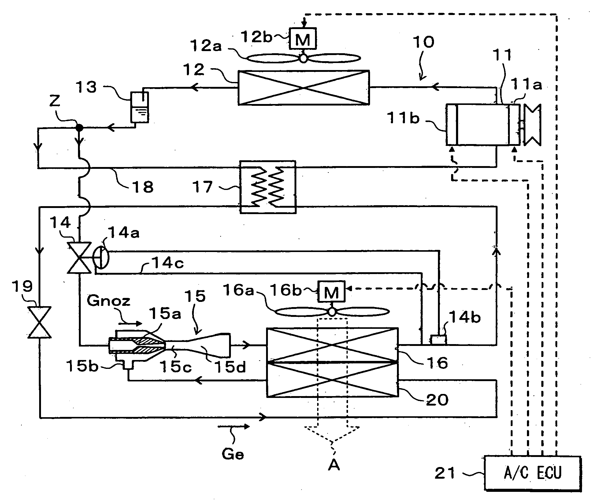
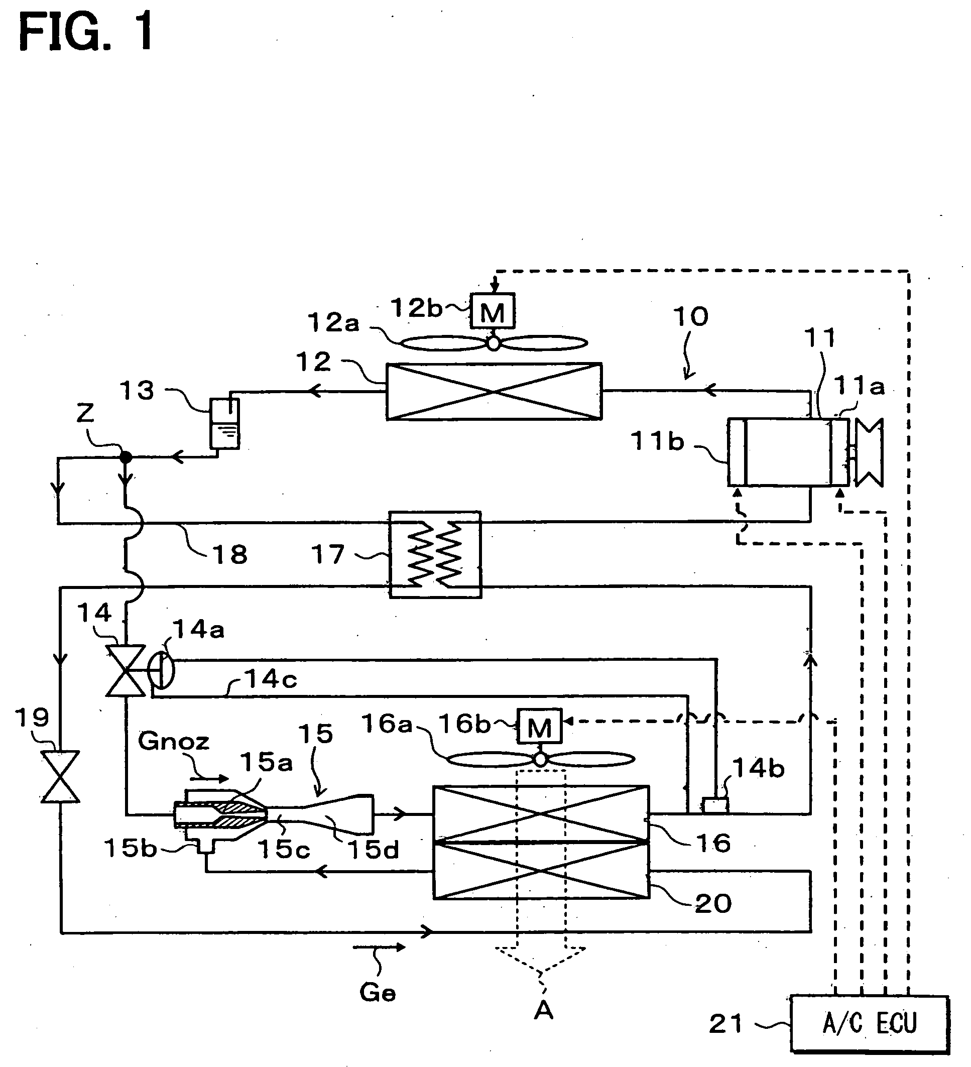
[0069]FIG. 1 illustrates an example in which an ejector cycle system 10 of the first embodiment is applied to a refrigerator device for vehicles. The refrigerator device for vehicles in this embodiment is so constructed as to lower the temperature inside a compartment to a very low temperature close to −20° C., for example.
[0070] In the ejector cycle system 10, a compressor 11 sucks in, compresses, and discharges refrigerant. The compressor 11 is rotationally driven by an engine for vehicle running (not shown) through an electromagnetic clutch 11a and a belt. This embodiment uses a swash plate-type variable displacement compressor whose discharge capacity can be continuously and variably controlled by external control signals.
[0071] More specific description will be given. The pressure in a swash plate chamber (not shown) is controlled utilizing the discharge pressure and the inlet pressure of the compressor 11. Thus, the angle of inclination of the swash plate is varied to change...
second embodiment
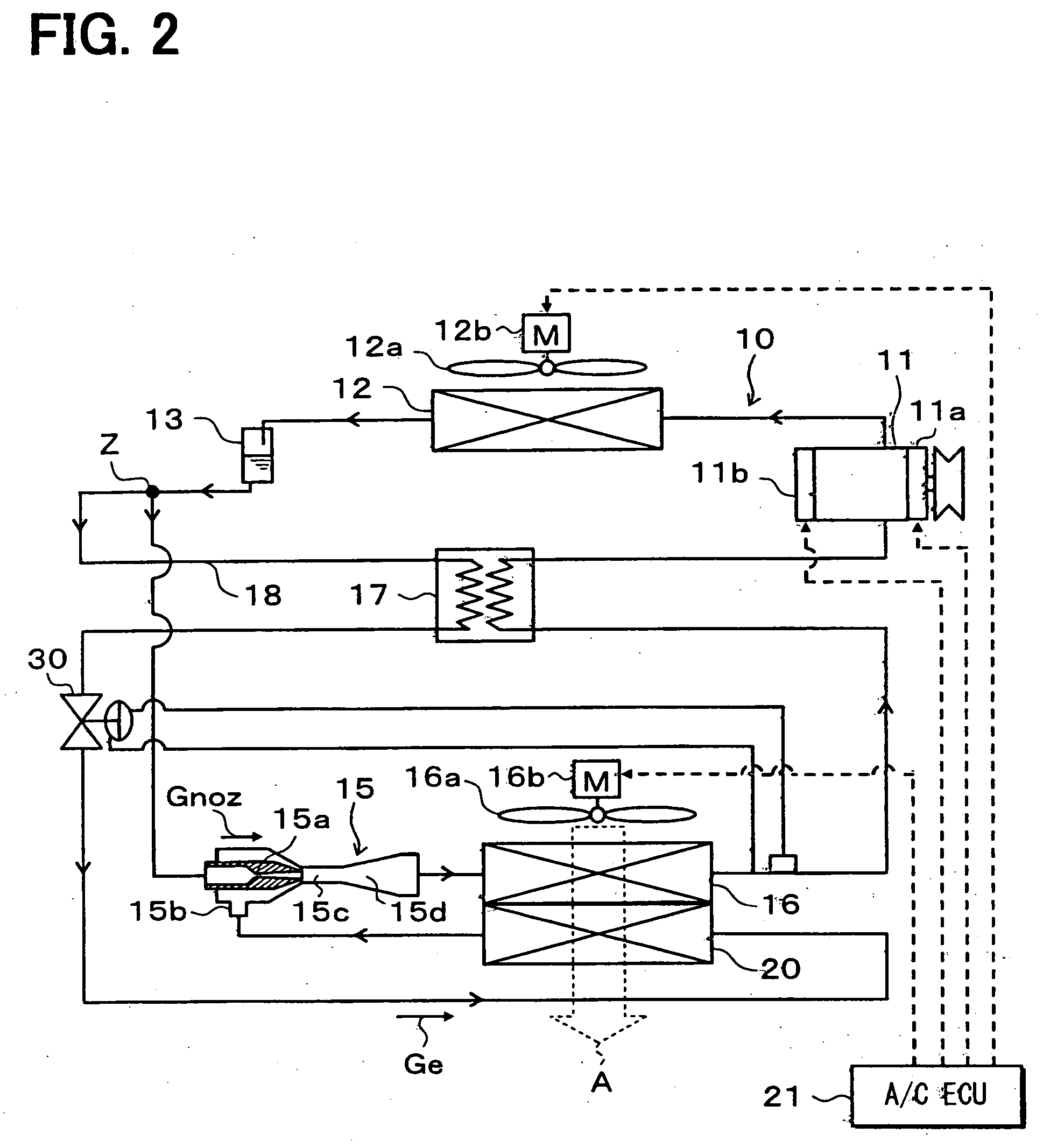
[0113] In the first embodiment, the variable throttling mechanism 14 is located between the branch portion Z and the ejector 15, and the fixed throttle 19 is located in the branch passage 18. In the second embodiment, as illustrated in FIG. 2, the variable throttling mechanism 14 and the fixed throttle 19 are disused, and a variable throttling mechanism 30 is provided in the branch passage 18.
[0114] The variable throttling mechanism 30 is a thermal expansion valve that adjusts the refrigerant flow rate so that the degree of superheat of refrigerant on the outlet side of the first evaporator 16 approaches a predetermined value. The construction of the thermal expansion valve can be the same as in the first embodiment. That is, the valve body of the variable throttling mechanism 30 makes a means for adjusting the flow ratio (η), and the temperature sensitive cylinder and equalizing pipe of the variable throttling mechanism 30 make a means for detecting the physical quantities related...
third embodiment
[0117] In the first embodiment, the variable throttling mechanism 14 is located between the branch portion Z and the ejector 15. In this third embodiment, as illustrated in FIG. 3, the variable throttling mechanism 14 shown in FIG. 1 is disused, and a variable throttling mechanism 31 is provided between the liquid receiver 13 and the branch portion Z.
[0118] The variable throttling mechanism 31 is a thermal expansion valve that adjusts the refrigerant flow rate so that the degree of superheat of refrigerant on the outlet side of the first evaporator 16 approaches a predetermined value. The construction of the thermal expansion valve is the same as in the first embodiment. That is, the valve body of the variable throttling mechanism 31 is a means for adjusting the refrigerant flow rate of the entire cycle; and the temperature sensitive cylinder and equalizing pipe of the variable throttling mechanism 31 are a means for detecting the physical quantities related to the state of refrige...
PUM
 Abstract
Description
Claims
Application Information