
Methods and apparatuses for purifying carbon filamentary structures

a carbon filamentary structure and purification method technology, applied in the direction of carbon nanotubes, gas current separation, open gradient mangetic separators, etc., can solve the problems of graphite shells with magnetic metal particles trapped therein, nanotubes can be functionalized or even damaged, and the purification method of nanotubes has a major drawback. , to achieve the effect of reducing the amount of carbon filamentary structures

Inactive Publication Date: 2007-01-04
INSTITUT NATIONAL DE LA RECHERCHE SCIENTIFIQUE
View PDF24 Cites 18 Cited by
  • Summary
  • Abstract
  • Description
  • Claims
  • Application Information

AI Technical Summary

Benefits of technology

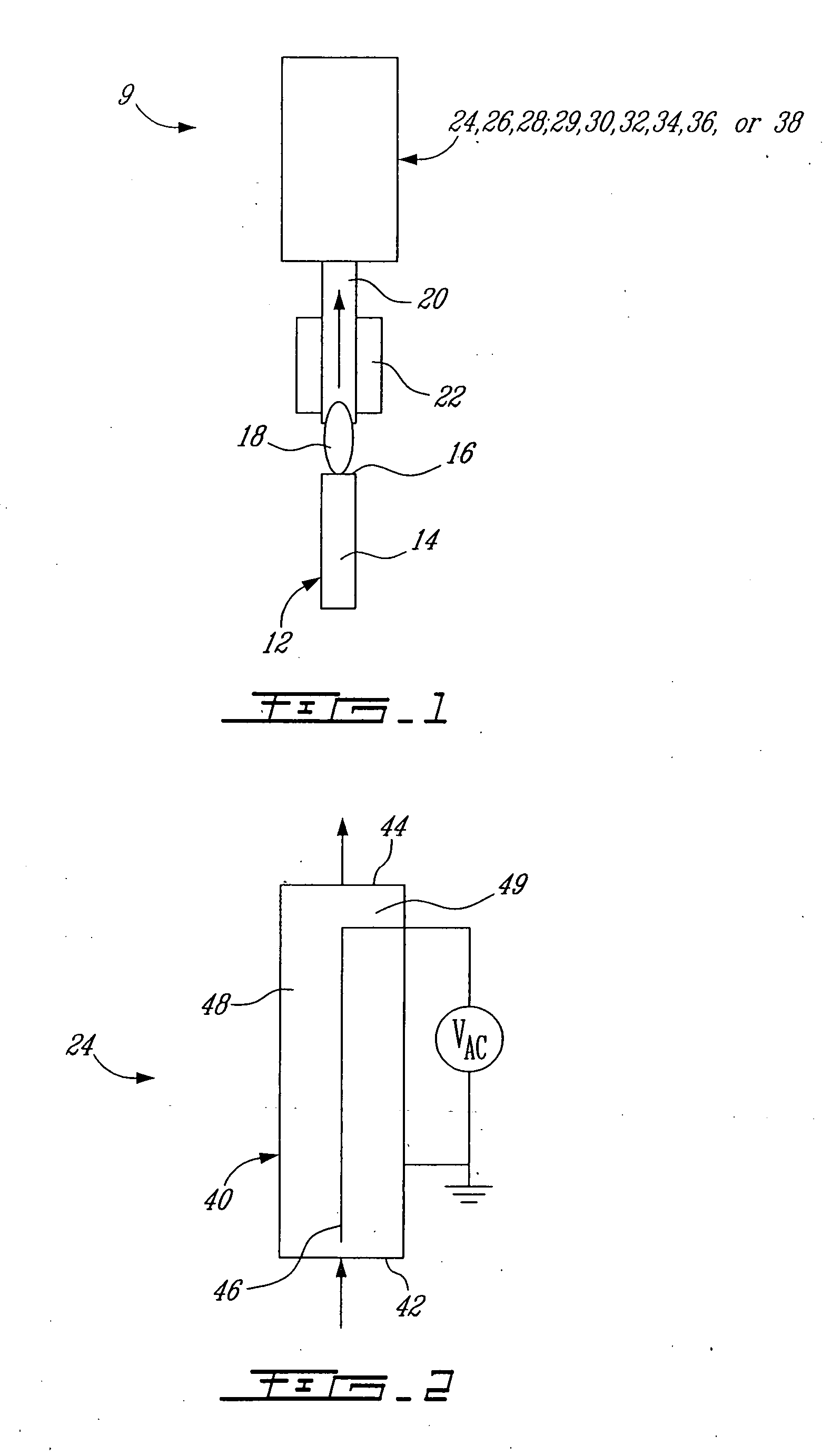
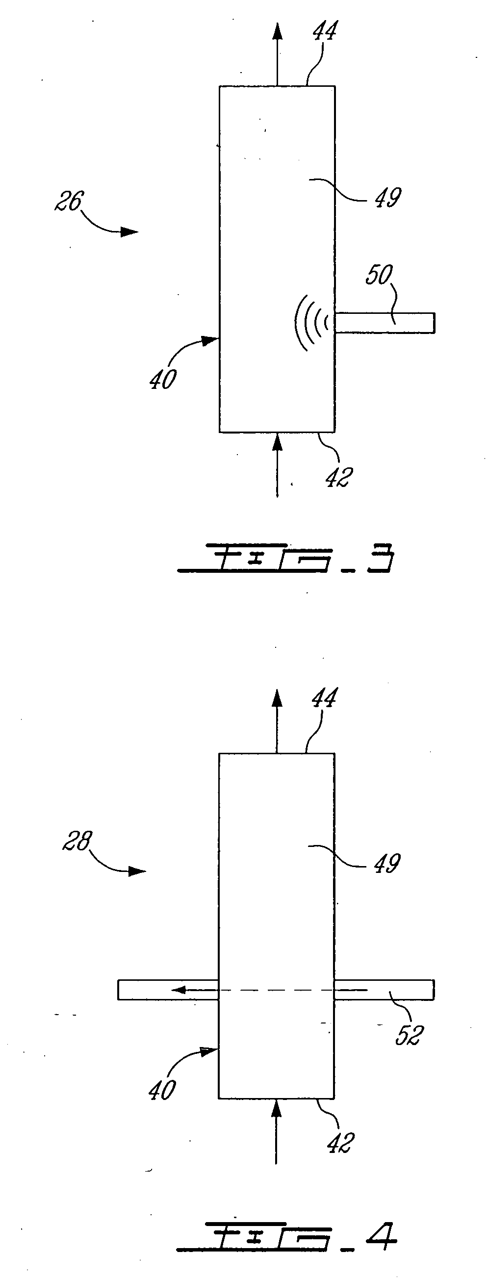
[0007] According to one aspect of the present invention, there is provided a method for treating a gaseous phase comprising carbon filamentary structures having metal particles attached or linked thereto, for separating at least a portion of the carbon filamentary structures from the metal particles. The method comprises submitting the gaseous phase to a disturbance, thereby reducing the amount of carbon filamentary structures having metal particles attached or linked thereto.

Problems solved by technology

Thus, the magnetic metal particles in their oxide form are bigger which eventually causes breaking or cracking of graphite shells having magnetic metal particles trapped therein.
Such a method of purifying nanotubes has a major drawback since the nanotubes can be functionalized or even be damaged.
It is also a time consuming, polluting and costly method.
The use of a liquid phase in the purification process can be time consuming since several steps such as filtration and drying are required.
Another major drawback in the synthesis of carbon nanotubes is that the methods that have been proposed so far are not continuous or in situ.
Therefore, several tasks and steps are required before obtaining a sufficient purity.

Method used


Image

  • Methods and apparatuses for purifying carbon filamentary structures
  • Methods and apparatuses for purifying carbon filamentary structures
  • Methods and apparatuses for purifying carbon filamentary structures

Examples


examples

[0180] The following examples represent only preferred embodiments of the present invention.

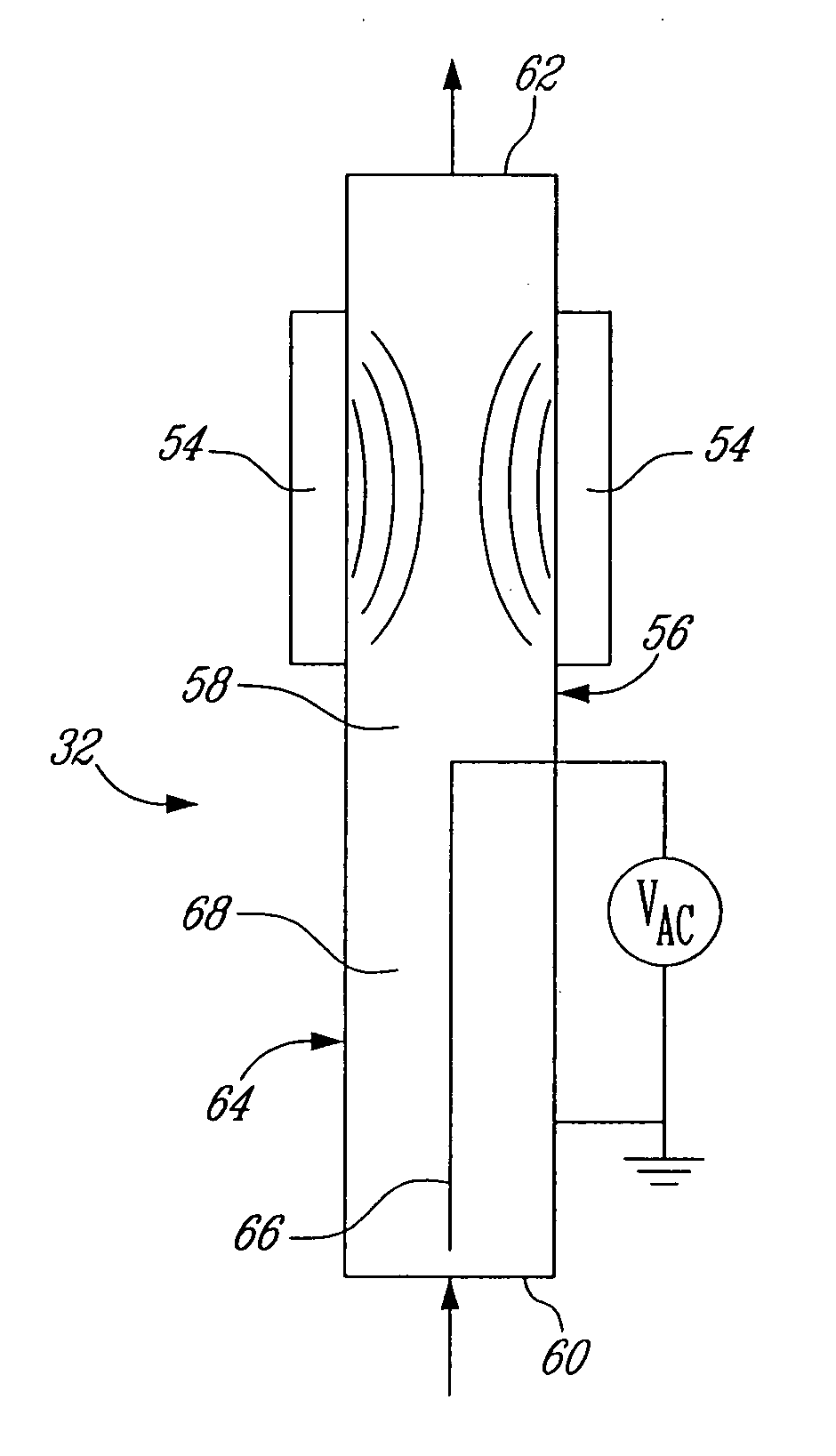
[0181] An experiment was carried out by using an apparatus for purifying carbon nanotubes according to a preferred embodiment of the invention. For this experiment, an apparatus similar to the one schematically represented in FIG. 10 was used without the action of the disturbance generator in order to verify the efficiency of the apparatus and more particularly the efficiency of the process when the carbon filamentary structures are only submitted to the action of the inhomogeneous magnetic field. It was in fact the equivalent of using the apparatus of FIG. 6. The apparatus for purifying nanotubes was used downstream of a plasma torch for producing single-wall carbon nanotubes. In order to study its effect, deposits on the wall and downstream of the apparatus have been collected. The plasma torch used was similar to the plasma torch represented in FIG. 1 of U.S. 2003 / 0211030, which is hereby...


PUM

PropertyMeasurementUnit
Magnetic fieldaaaaaaaaaa
Structureaaaaaaaaaa

Abstract

There is provided a method for purifying carbon filamentary structures contaminated with magnetic metal particles. The method comprises submitting a gaseous phase comprising said carbon filamentary structures contaminated with magnetic metal particles, to an inhomogeneous magnetic field for at least partially trapping said magnetic metal particles, thereby reducing the proportion of said magnetic metal particles present in said gaseous phase. The method is particularly useful for purifying carbon filamentary structures such as multi-wall carbon nanotubes, single-wall carbon nanotubes or carbon fibers. An apparatus for purifying such carbon filamentary structures contaminated with magnetic metal particles is also provided.

Description

CROSS-REFERENCE TO RELATED APPLICATION [0001] The present application claims priority on U.S. provisional application No. 60 / 664,952 filed on Mar. 25, 2005, which is incorporated herein by reference in its entirety.FIELD OF THE INVENTION [0002] The present invention relates to improvements in the field of carbon filamentary structures production. More particularly, the invention relates to improved methods and apparatuses for purifying carbon filamentary structures such as carbon fibres, single-wall carbon nanotubes or multi-wall carbon nanotubes. BACKGROUND OF THE INVENTION [0003] Carbon nanotubes are available either as multi-wall or single-wall nanotubes. Multi-wall carbon nanotubes have exceptional properties such as excellent electrical and thermal conductivities. They have applications in numerous fields such as storage of hydrogen (C. Liu, Y. Y. Fan, M. Liu, H. T. Cong, H.M. Cheng, M. S. Dresselhaus, Science 286 (1999), 1127; M. S. Dresselhaus, K. A Williams, P. C. Eklund, MR...

Claims


Application Information

Patent Timeline
IPC IPC(8): B03C1/00B07B4/00C01B31/02B07B7/00
CPCB82Y30/00B82Y40/00C01B31/026C01B2202/02C01B2202/06B03C3/06B03C1/015B03C1/035B03C1/14B03C3/017D01F11/16C01B32/17
Inventor LAROUCHE, FREDERICSMILJANIC, OLIVIERSTANSFIELD, BARRY L.
Owner INSTITUT NATIONAL DE LA RECHERCHE SCIENTIFIQUE
Learn More