Polymer bushing and cable terminal end connector using the same

a technology of polymer bushings and cable terminals, which is applied in the direction of cable fittings, electrical cable installations, electrical apparatus, etc., can solve the problems of secondary disaster, degradation of the characteristic of pollution resistance voltage of porcelain jackets, and heavy weight of porcelain jackets, so as to reduce the length of the bushings, the effect of reducing the weight and slimming the structur

Inactive Publication Date: 2007-01-04
SWCC SHOWA CABLE SYST CO LTD
View PDF7 Cites 17 Cited by
  • Summary
  • Abstract
  • Description
  • Claims
  • Application Information

AI Technical Summary

Benefits of technology

[0031] In the first place, since the surface electric field of the polymer bushing can be mitigated by the electric-field stress-control layer which is disposed on the interface between the insulation sleeve and the polymer clad body, the insulation sleeve can be thinned, with the result that the polymer bushing can be made lighter in weight and slimmer in structure than the prior-art polymer bushing shown in FIG. 10.
[0032] Secondly, owing to the mitigation of the surface electric field of the polymer bushing, reduction in bushing length can be achieved.
[0033] Thirdly, the out-door termination which is lighter in weight and slimmer in structure is applied to an ultrahigh voltage cable, whereby reduction in subsidiary works can be achieved.
[0034] Fourthly, in the case where the receiving port of the insulation sleeve is located at the position lower than the polymer clad body, the polymer bushing can achieve the compatibility of the types of bushings and the simplification of operating steps likewise to the prior-art polymer bushing shown in FIG. 10, and it can be installed in a flexible manner.
[0035] Fifthly, since the embedment metal fitting is embedded in the polymer bushing and is made integral with a bottom metal fitting, the polymer bushing can be mechanically reinforced, and it can be easily and stably mounted on a mounting stand or the like through the bottom metal fitting.
[0036] Sixthly, in the case where the bend is provided at the intermediate part of the polymer bushing, a separation can be satisfactorily ensured even when the polymer bushing is installed in a substation or the like having a low ceiling.

Problems solved by technology

In the first place, there has been the drawback that, since the epoxy seat for receiving the stress cone exists inside the porcelain jacket, the diameter of the porcelain jacket enlarges accordingly, resulting in the heavy weight of the porcelain jacket.
Secondly, there has been the drawback that, when the outside diameter of the porcelain jacket enlarges, the projection cross-sectional area thereof becomes large, resulting in the degradation of the characteristic of the pollution withstand voltage of the porcelain jacket, so an elongated porcelain jacket must be used to keep a predetermined characteristic of pollution withstand voltage.
Thirdly, the porcelain jacket is filled with the insulating compound, so that when the porcelain jacket has broken down, the insulating compound might flow out of this porcelain jacket to cause a secondary disaster.
Fourthly, there has been the drawback that, since the components such as epoxy seat, upper covering and clamp metal fitting are required, a large number of components and a complicated structure are involved.
In the cable termination (I), however, the bushing is formed of a polymer being a high-molecular material, so that a water content might penetrate therethrough from outside to mix into the insulating oil or insulating gas contained in the polymer bushing, and to deteriorate the performance of the insulating oil or insulating gas.
This results in the drawback that an elongated polymer bushing must be used for attaining enhancement in the characteristic of pollution withstand voltage.
Secondly, as the service voltage of the cable termination becomes higher, the polymer bushing 55 is lengthened more, and the handling of the polymer bushing 55 in an installation work becomes more difficult due to the larger length conjointly with the heavier weight.

Method used


Image

  • Polymer bushing and cable terminal end connector using the same
  • Polymer bushing and cable terminal end connector using the same
  • Polymer bushing and cable terminal end connector using the same

Examples


Embodiment Construction

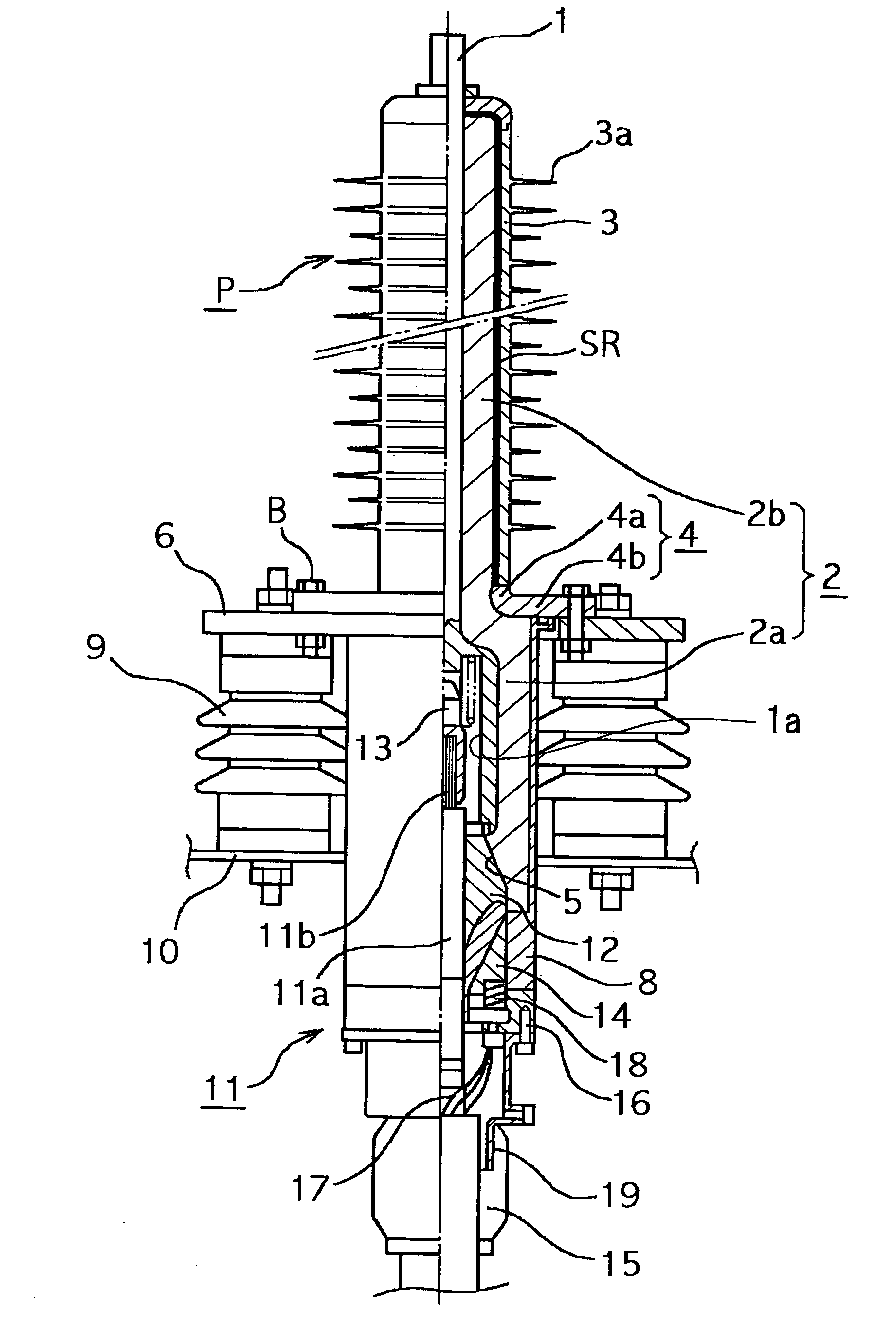
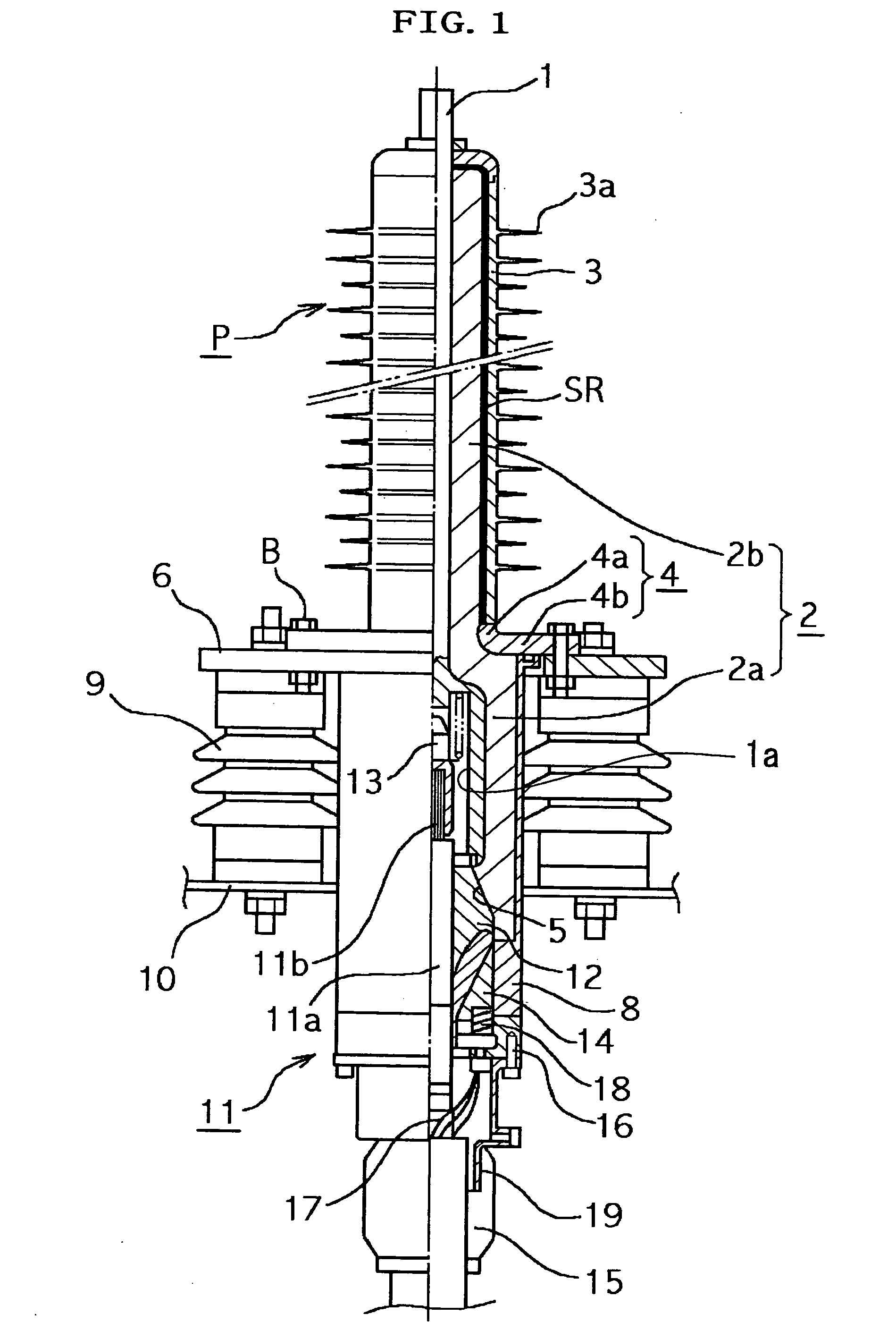
[0047] Now, the preferred embodiments of a polymer bushing and a cable termination using the polymer bushing, in the present invention, will be described with reference to the drawings. Here, FIG. 1 shows a partly sectional view of an out-door termination for a CV cable of 22-77 kV class as uses the polymer bushing in the invention.

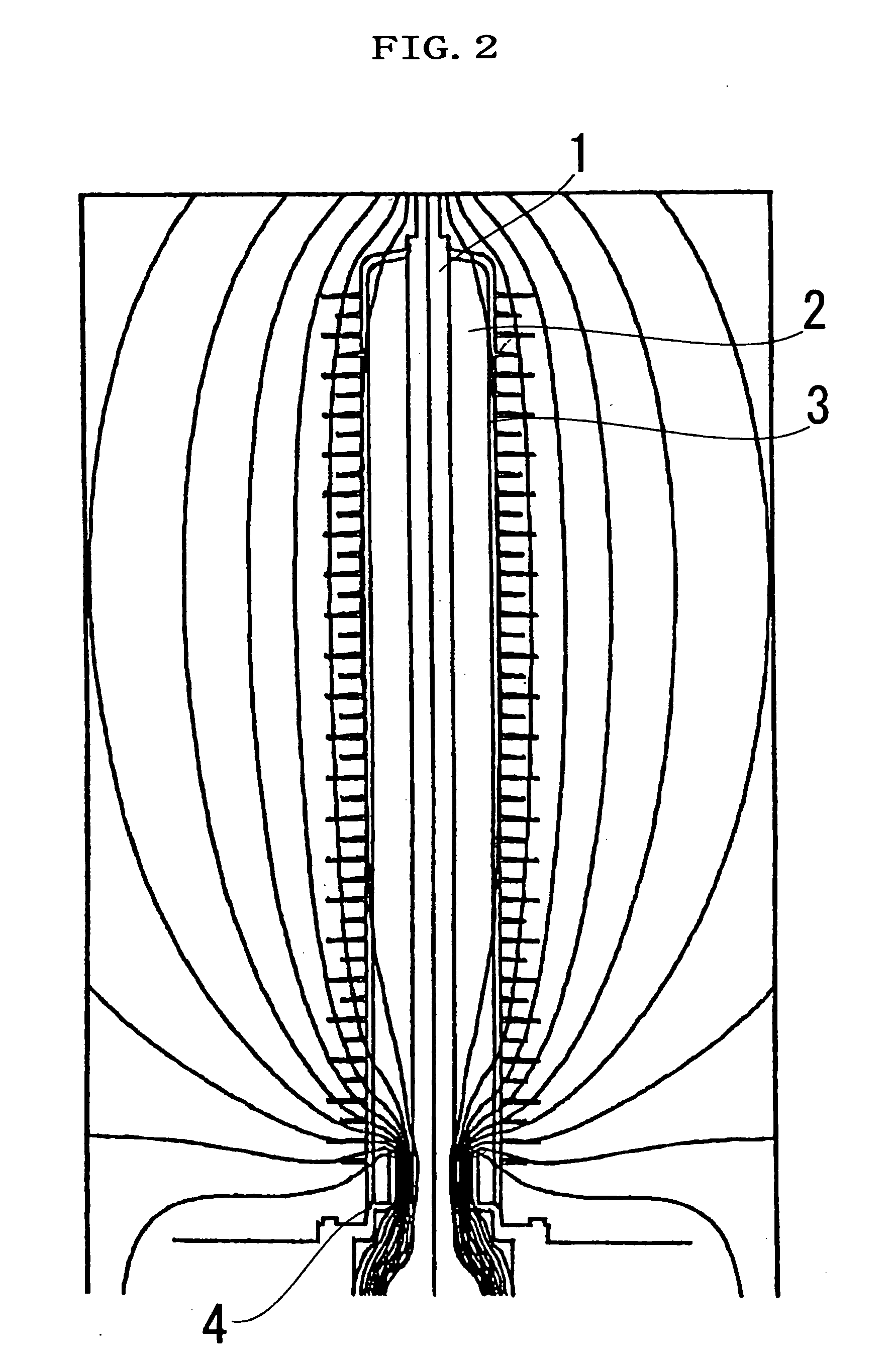
[0048] Referring to FIG. 1, the polymer bushing P of the invention includes a conductor draw-out bar 1 which is centrally disposed and which has a conductor insertion hole 1a at the lower end part thereof, a hard insulation sleeve 2 which is provided around the outer periphery of the conductor draw-out bar 1, an electric-field stress-control layer SR which is provided around the outer periphery of the insulation sleeve 2, and a polymer clad body 3 which is provided around the outer periphery of the electric-field stress-control layer SR. Here, the insulation sleeve 2 is formed of a material of high mechanical strength, for example, a hard plastic resin s...


PUM

PropertyMeasurementUnit
relative permittivityaaaaaaaaaa
electrical-field stressaaaaaaaaaa
electric-field stressaaaaaaaaaa

Abstract

It is intended to achieve the weight reduction, sliming, and downsizing of bushings, compatibility of types of bushings, and simplification of operating steps. A polymer bushing comprises a conductor draw-out bar (1) having a conductor insertion hole (1a) in the lower end, a hard insulation sleeve (2) installed around the outer periphery of the conductor draw-out bar (1), a polymer clad body (3) installed around the outer periphery of the insulation sleeve (2), and an electric field stress-control layer installed on the interface between the insulation sleeve (2) and the polymer clad body (3). The insulation sleeve (2) comprises a large-diameter insulation sleeve (2a) installed around the outer periphery of the lower region of the conductor draw-out bar (1), and a small-diameter insulation sleeve (2b) installed around the outer periphery of a portion of the conductor draw-out bar (1) excluding the front end. An embedment metal part (4) for electric field mitigation purposes is embedded in a portion of connection between the large-and small-diameter insulation sleeves (2a, 2b). Further, installed at the lower end of the large-diameter insulation sleeve (2a) is a cone-shaped receiving port (5) for receiving the stress cone (13) of a cable terminal (11), the receiving port (5) communicating with the conductor insertion hole (1a) in the conductor draw-out bar (1).

Description

TECHNICAL FIELD [0001] This invention relates to a polymer bushing and a cable termination using the polymer bushing. More particularly, it relates to a polymer bushing which can achieve the simplification of a structure, the reductions of a weight, a size and a length, and the facilitation of on-site execution, which need not be filled with an insulating compound such as insulating oil or insulating gas, and which is well suited for installation in a substation of low ceiling or on the cross arm of a pylon, and a cable termination which uses the polymer bushing. BACKGROUND ART [0002] Heretofore, as a cable termination of this type, one constructed as shown in FIG. 8 has been known. Referring to the figure, the cable termination in the prior art includes a cable terminal 20, and a porcelain jacket 21 which envelops the cable terminal 20 and which is filled with an insulating compound 22 such as insulating oil or insulating gas. [0003] Here, an annular bottom metal fitting 23 is moun...

Claims


Application Information

Patent Timeline
Patent Type & Authority Applications(United States)
IPC IPC(8): H02G15/00H01B17/26H01B17/00H02G1/14H02G15/064H02G15/068
CPCH02G15/068H01B17/265H01B17/30
Inventor ADACHI, KAZUHISANOBUYUKI, SEMA
Owner SWCC SHOWA CABLE SYST CO LTD
Why Eureka
Try Eureka