System and method for recycling waste into energy

a technology of waste and energy, applied in the direction of solid fuel combustion, lighting and heating apparatus, combustion types, etc., can solve the problems of no effective way of monitoring the vacuum within the system at potential leakage sites, and the application of a metering mechanism for waste material amoun

Active Publication Date: 2007-01-04
EFFICIEN TECH
View PDF25 Cites 23 Cited by
  • Summary
  • Abstract
  • Description
  • Claims
  • Application Information

AI Technical Summary

Benefits of technology

[0006] In one embodiment, a system for recycling solid waste into energy utilizes solid waste particles having a cross-sectional size less than 1 inch in length. The system comprises a heated enclosure having an interior chamber and a plurality of internal baffles within the heated chamber, one or more input conveyors for inputting waste particles to the heated enclosure, and a flow line within the heated enclosure in fluid communication with the one or more input conveyors for receiving waste particles and positioned with respect to the plurality of baffles to provide a temperature gradient along the flow line of at least 150F°, thereby producing hydrocarbon vapors and residual solids. A heated conveyor within the flow line mechanically moves the waste particles and the residual solids along the flow line. A heated rotary drum is provided in fluid communication with the flow line for receiving the waste particles and the residual solids, with the rotary drum having an interior temperature of from 730° F. to 800° F. for generating hydrocarbon vapors and carbon black solids. A condenser is in fluid communication with the flow line and the rotary drum for receiving the vapors from the flow line and the rotary drum and outputting liquids including hydrocarbons and gas including hydrocarbons. One or more discharge conveyors are provided for discharging the carbon black solids from the rotary drum. Two or more input control valves are each positioned along the one or more input conveyors for sealing vacuum downstream from the one or more input conveyors, with each input control valve having two or more axially spaced closure gates. Similarly, two or more discharge control valves are positioned along the one or more discharge conveyors for sealing vacuum upstream from the one or more discharge conveyors, with each discharge control valve having two or more axially spaced closure gates. A vacuum pump maintains a selective vacuum of less than 5 inches of water between the two or more input valves and the two or more discharge valves, such that hydrocarbon vapors are drawn from the flow line and the rotary drum into the condenser.

Problems solved by technology

The prior art systems known to Applicants do not provide a mechanism for metering the amount of waste material input to the heated enclosure, and contain no effective way of monitoring the vacuum within the system at potential leak sites.

Method used


Image

  • System and method for recycling waste into energy
  • System and method for recycling waste into energy
  • System and method for recycling waste into energy

Examples


Embodiment Construction

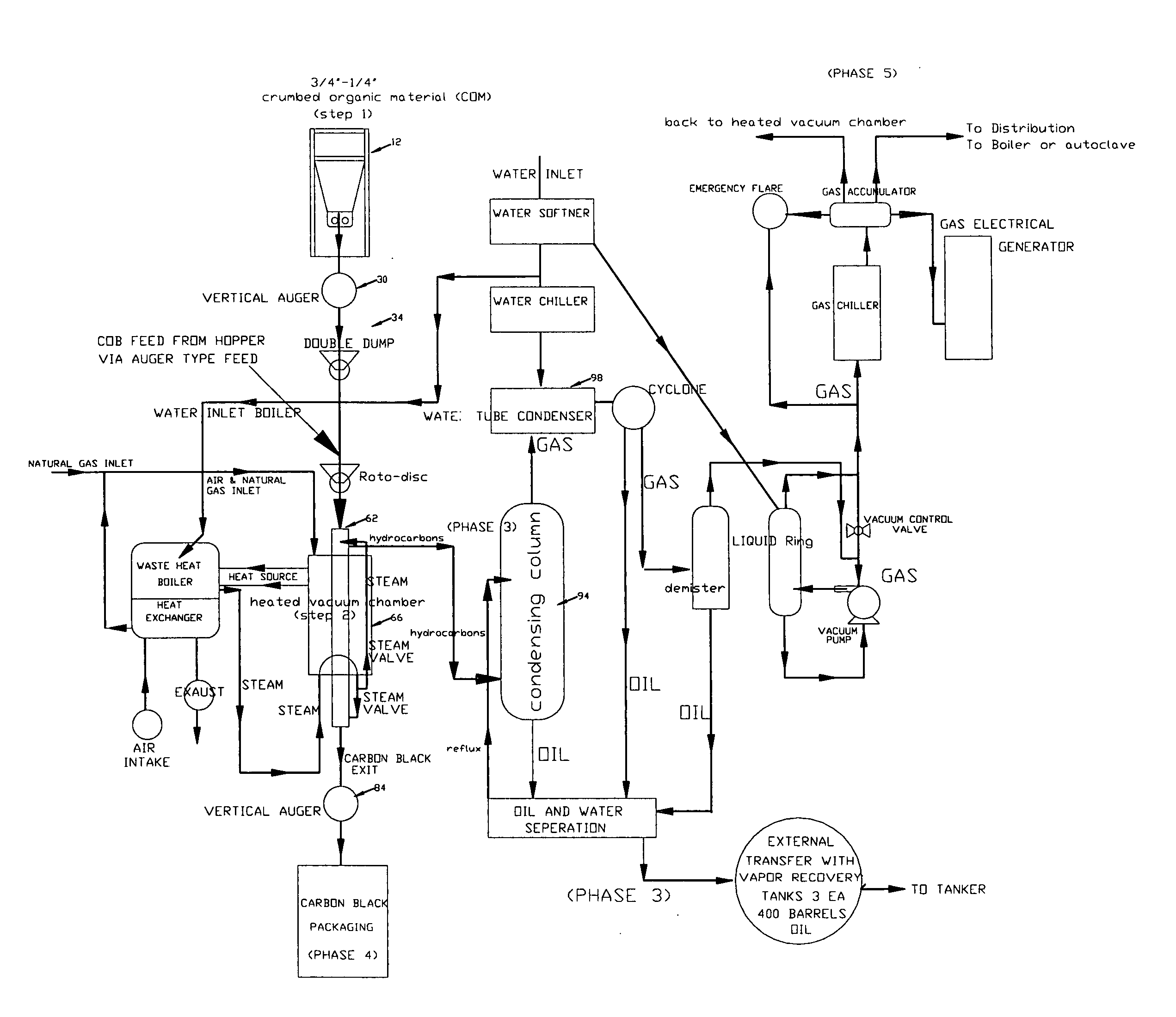
[0018] A system according to the present invention is well suited for converting various types of waste materials into energy, and for the purposes of explanation as discussed below is used to convert waste rubber particles of a type formed from worn tires into energy. Those skilled in the art will appreciate, however, that the system and method disclosed herein may be used to convert various other types of waste materials into energy as discussed below.

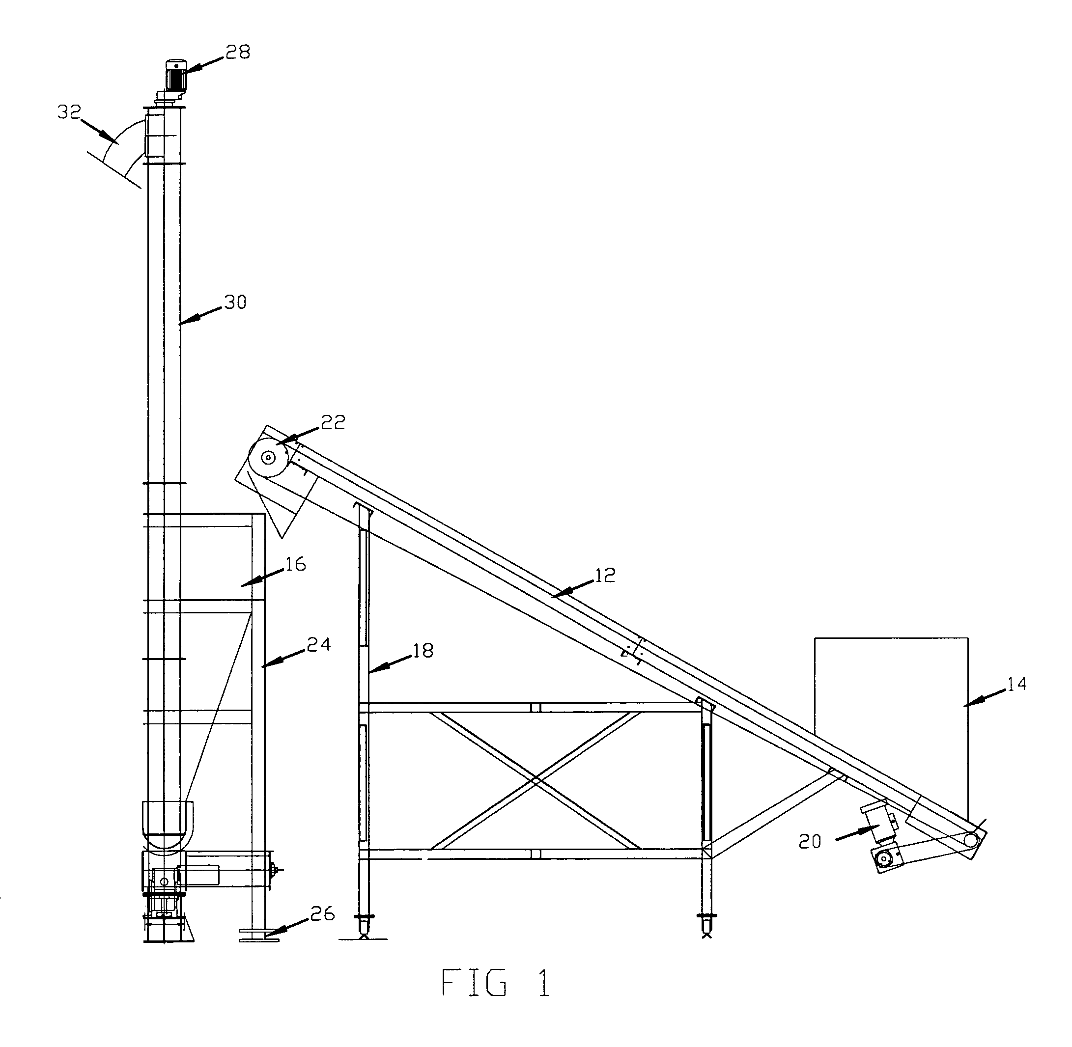
[0019]FIG. 1 illustrates a belt conveyor 12 which may be used to convey rubber particles from an initial dump hopper 14 into a staging hopper 16. The conveyor 12 may be supported on a suitable frame structure 18, with a motor and gearbox assembly 20 used to power the conveyor 12. A magnetic drum 22 is provided adjacent a discharge end of the conveyor 12 for minimizing the amount of metal input to the hopper 16.

[0020] The hopper 16 may be provided with a support structure 24 which includes a plurality of load cells 26 for measuring ...


PUM

PropertyMeasurementUnit
lengthaaaaaaaaaa
temperatureaaaaaaaaaa

Abstract

A system for recycling solid waste into energy includes a heated enclosure 66, one or more input conveyors 60, 67 move waste materials through the heated enclosure, provide a flow line with a temperature gradient of at least 150F°, and mechanically move the waste particles and the residual solids along the flow line. A heated rotary drum 74 is in fluid communication with the flow line, and condenser unit 94, 98 receive vapors from the flow line and the rotary drum and output hydrocarbons. One or more discharge conveyors 76 discharge carbon black from the rotary drum. Control valves 80, 82 seal a vacuum downstream from the discharge conveyors, and control valves 34, 46 seal vacuum upstream from the one or more input conveyors. Various types of vacuum pumps may be used to maintain a selected vacuum between the control valves.

Description

RELATED CASE [0001] This application claims priority from U.S. Ser. No. 60 / 595,416 filed Jan. 12, 2005.FIELD OF THE INVENTION [0002] The present invention relates to equipment and techniques for recycling waste into energy, wherein a heated enclosure and a condenser operate under a selected vacuum maintained by a vacuum pump. Waste material is moved through the heated enclosure in a first direction, while hydrocarbon vapors are drawn toward the condenser in an opposing second direction. BACKGROUND OF THE INVENTION [0003] Various types of devices have been experimentally used for recycling waste into energy. Some devices are particularly intended for disposing of solid waste, such as rubber particles from used tires. One type of experimental device utilized a heated enclosure with an interior chamber and a conveyor for inputting waste particles to the heated enclosure. A condenser received vapors from the heated enclosure and output liquid hydrocarbons and gas hydrocarbons. Vacuum pu...

Claims


Application Information

Patent Timeline
Patent Type & Authority Applications(United States)
IPC IPC(8): C10B21/00C10B1/10
CPCB09B3/00B09B3/0083C10G1/10C10B53/07C10B47/02Y02P20/143B09B3/40
Inventor CAULEY, PHILLIP L.EDWARDS, TRACY L.
Owner EFFICIEN TECH
Why Eureka
Try Eureka