
Low Emission Power Generation and Hydrocarbon Recovery Systems and Methods

a technology of hydrocarbon recovery and power generation, applied in the field of low emission power generation, can solve the problems of increasing fuel demand, reducing power generation efficiency, and reducing power production, and achieve the effect of improving hydrocarbon recovery and enhancing oil recovery reservoirs

Active Publication Date: 2011-01-06
EXXONMOBIL UPSTREAM RES CO
View PDF45 Cites 113 Cited by
  • Summary
  • Abstract
  • Description
  • Claims
  • Application Information

AI Technical Summary

Benefits of technology

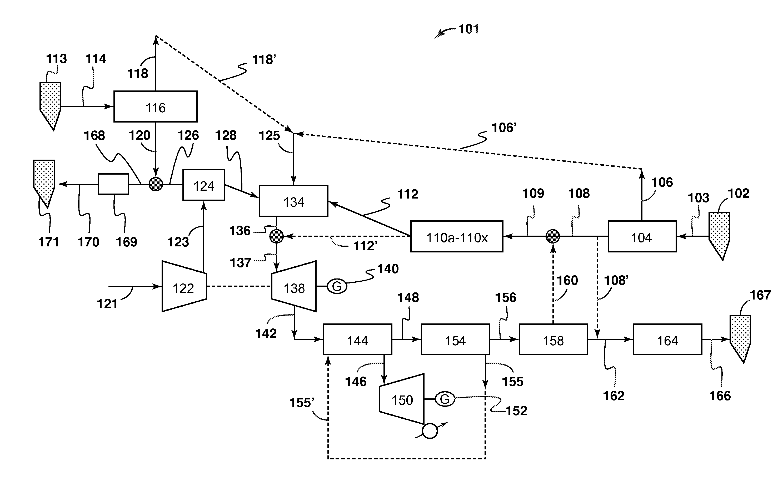
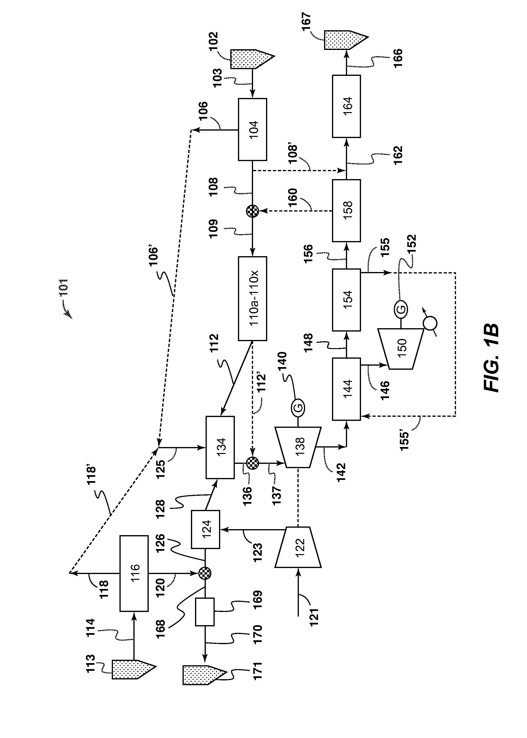
[0011]Another embodiment of the present invention discloses a method of improved hydrocarbon recovery. The method includes separating air into a high purity oxygen stream and a high purity nitrogen stream; providing a gaseous control fuel stream; combusting in a combustor, at least the gaseous control fuel stream and the high purity oxygen stream to form a gaseous combustion stream having carbon dioxide and water; receiving the gaseous combustion stream having carbon dioxide and water into a power generation system, wherein the power generation system produces at least a compressed gaseous substantially carbon dioxide stream; injecting at least a portion of the compressed gaseous substantially carbon dioxide stream into an enhanced oil recovery reservoir; and injecting at least a portion of the high purity nitrogen stream into a pressure maintenance reservoir.

Problems solved by technology

However, both of these solutions are expensive and reduce power generation efficiency, resulting in lower power production, increased fuel demand and increased cost of electricity to meet domestic power demand.
However, there are no commercially available gas turbines that can operate in such a cycle and the power required to produce high purity oxygen significantly reduces the overall efficiency of the process.
This approach fails to teach or suggest a solution to the efficiency drag from the oxygen plant.
The '696 publication also requires a stand-alone oxygen plant or air separation plant, and fails to teach or suggest a working gas power turbine configuration.

Method used


Image

  • Low Emission Power Generation and Hydrocarbon Recovery Systems and Methods
  • Low Emission Power Generation and Hydrocarbon Recovery Systems and Methods
  • Low Emission Power Generation and Hydrocarbon Recovery Systems and Methods

Examples


Embodiment Construction

[0025]In the following detailed description section, the specific embodiments of the present invention are described in connection with preferred embodiments. However, to the extent that the following description is specific to a particular embodiment or a particular use of the present invention, this is intended to be for exemplary purposes only and simply provides a description of the exemplary embodiments. Accordingly, the invention is not limited to the specific embodiments described below, but rather, it includes all alternatives, modifications, and equivalents falling within the true spirit and scope of the appended claims.

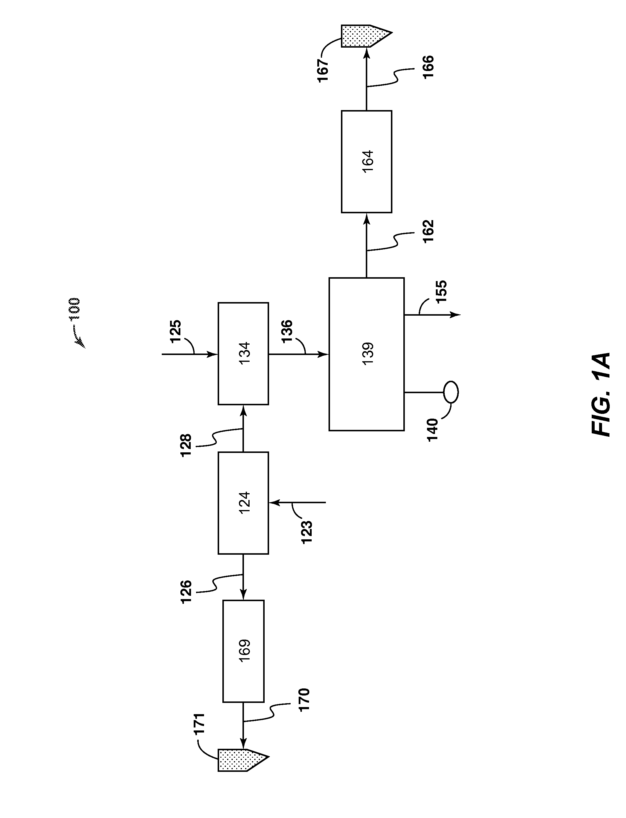
[0026]At least one benefit of the system is integration of two types of recovery processes to produce two types of injection gas (nitrogen and CO2) for additional hydrocarbon recovery. To accomplish this air is first compressed. The heat generated during compression may be captured and used for power generation or salt water desalination. The cool compressed...


PUM


Abstract

Methods and systems for low emission power generation in hydrocarbon recovery processes are provided. One system includes integrated pressure maintenance and miscible flood systems with low emission power generation. An alternative system provides for low emission power generation, carbon sequestration, enhanced oil recovery (EOR), or carbon dioxide sales using a hot gas expander and external combustor. Another alternative system provides for low emission power generation using a gas power turbine to compress air in the inlet compressor and generate power using hot carbon dioxide laden gas in the expander. Other efficiencies may be gained by incorporating heat cross-exchange, a desalination plant, co-generation, and other features.

Description

CROSS REFERENCE TO RELATED APPLICATIONS[0001]This application claims the benefit of U.S. Provisional Application No. 61 / 072,292, filed 28 Mar. 2008 and U.S. Provisional Application No. 61 / 153,508, filed 18 Feb. 2009.FIELD OF THE INVENTION[0002]Embodiments of the invention relate to low emission power generation in hydrocarbon recovery processes. More particularly, embodiments of the invention relate to methods and apparatuses for utilizing nitrogen, oxygen, carbon dioxide, and hydrocarbon fuel to generate power in a very low emission hydrocarbon recovery process.BACKGROUND OF THE INVENTION[0003]This section is intended to introduce various aspects of the art, which may be associated with exemplary embodiments of the present invention. This discussion is believed to assist in providing a framework to facilitate a better understanding of particular aspects of the present invention. Accordingly, it should be understood that this section should be read in this light, and not necessarily...

Claims


Application Information

Patent Timeline
IPC IPC(8): F02C6/00F02C7/22
CPCF01K23/068Y02E20/18Y02E20/16Y02E20/14Y02C10/14Y02E20/185Y02C10/00E21B43/164E21B43/18E21B43/40F01K23/10Y02P90/70Y02E20/34Y02C20/40
Inventor MINTA, MOSESMITTRICKER, FRANKLIN F.RASMUSSEN, PETERSTARCHER, LOREN K.RASMUSSEN, CHAD C.WILKINS, JAMES T.MEIDEL JR., RICHARD W.
Owner EXXONMOBIL UPSTREAM RES CO
Learn More