Low Emission Power Generation and Hydrocarbon Recovery Systems and Methods

a technology of hydrocarbon recovery and power generation, applied in the direction of machines/engines, mechanical equipment, borehole/well accessories, etc., can solve the problems of reducing power generation efficiency, reducing power production, and the world's toughest energy challenges

Inactive Publication Date: 2011-01-06
EXXONMOBIL UPSTREAM RES CO
View PDF101 Cites 124 Cited by
  • Summary
  • Abstract
  • Description
  • Claims
  • Application Information

AI Technical Summary

Benefits of technology

[0014]In a sixth embodiment of the present disclosure, additional alternative methods of producing oil are provided. The methods include separating air in an air separation unit configured to generate a substantially nitrogen stream and a substantially oxygen stream; producing a syngas stream comprising carbon monoxide, carbon dioxide, and hydrogen using a reactor unit configured to utilize the substantially oxygen stream, a hydrocarbon fuel stream, and a steam stream; converting at least a portion of the carbon monoxide to carbon dioxide in a gas-water shift reactor to form a shifted stream; separating the shifted stream into a carbon dioxide stream and a hydrogen stream; injecting at least a portion of the separated carbon dioxide stream into an enhanced oil recovery reservoir; and producing hydrocarbons from the enhanced oil recovery reservoir.

Problems solved by technology

Efficiently producing hydrocarbons while reducing GHG emissions is one of the world's toughest energy challenges.
However, both of these solutions are expensive and reduce power generation efficiency, resulting in lower power production, increased fuel demand and increased cost of electricity to meet domestic power demand.
However, there are no commercially available gas turbines that can operate in such a cycle and the power required to produce high purity oxygen significantly reduces the overall efficiency of the process.

Method used


Image

  • Low Emission Power Generation and Hydrocarbon Recovery Systems and Methods
  • Low Emission Power Generation and Hydrocarbon Recovery Systems and Methods
  • Low Emission Power Generation and Hydrocarbon Recovery Systems and Methods

Examples


Embodiment Construction

[0025]In the following detailed description section, the specific embodiments of the present invention are described in connection with preferred embodiments. However, to the extent that the following description is specific to a particular embodiment or a particular use of the present invention, this is intended to be for exemplary purposes only and simply provides a description of the exemplary embodiments. Accordingly, the invention is not limited to the specific embodiments described below, but rather, it includes all alternatives, modifications, and equivalents falling within the true spirit and scope of the appended claims.

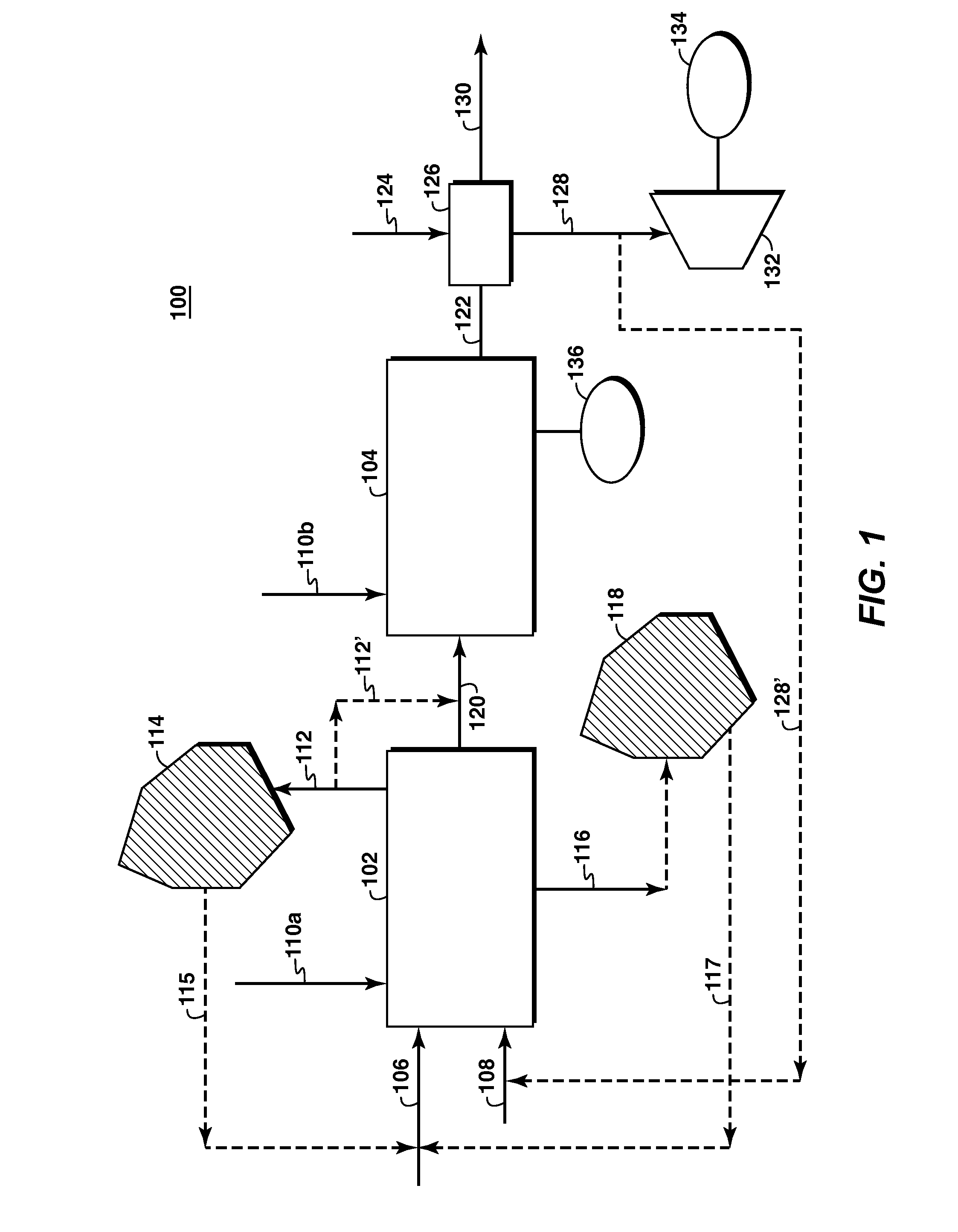
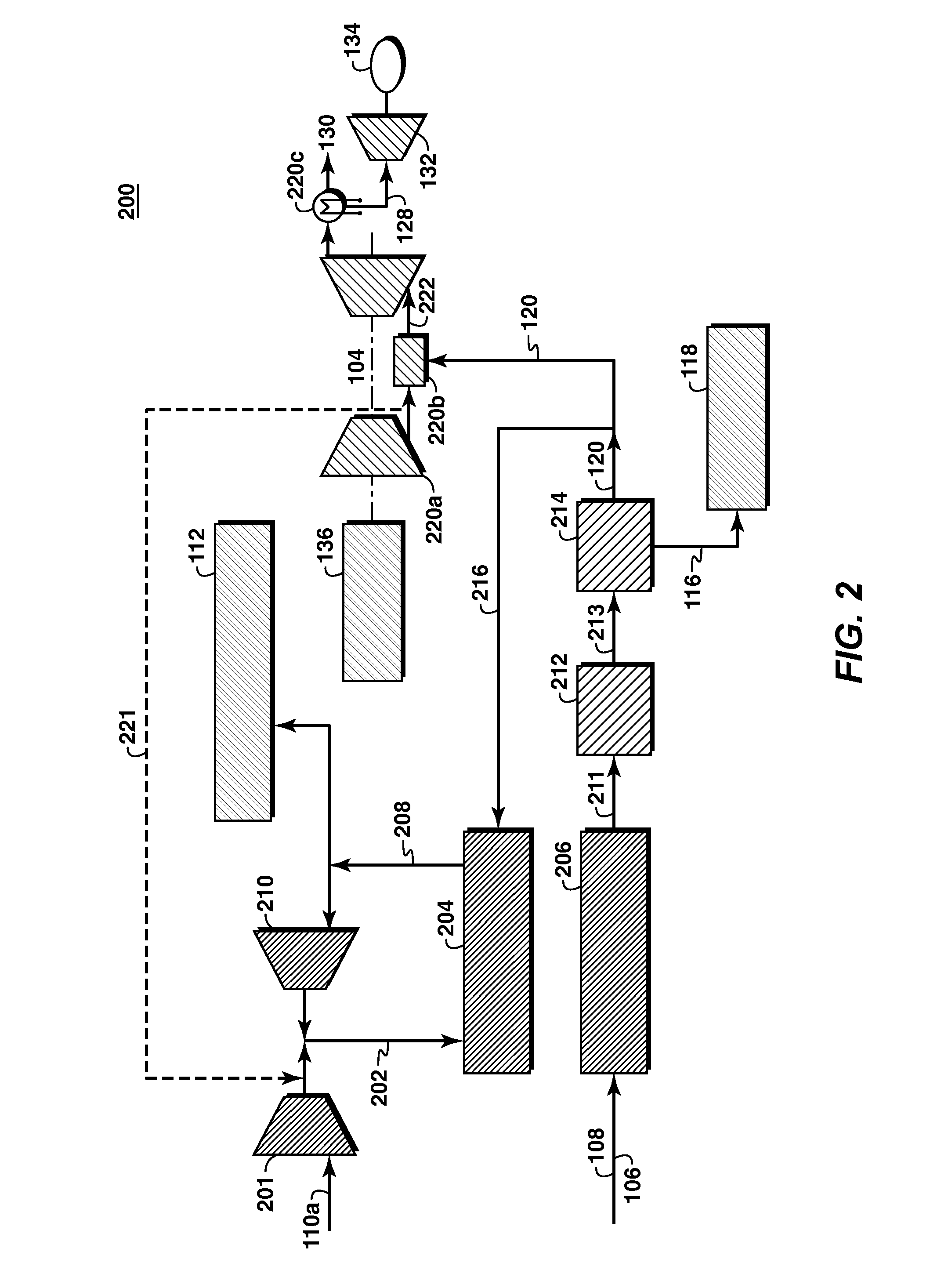
[0026]At least one benefit of the system is integration of two types of recovery processes to produce two types of injection gas (nitrogen and CO2) for additional hydrocarbon recovery. One exemplary approach to produce N2, CO2 and power to take advantage of the catalytic combustion step within a Pressure Swing Reforming (PSR) process to reactively remove oxy...


PUM


Abstract

Methods and systems for low emission power generation in hydrocarbon recovery processes are provided. One system includes integrated pressure maintenance and miscible flood systems with low emission power generation. The system may also include integration of a pressure swing reformer (PSR), air-blown auto-thermal reformer (ATR), or oxygen-blown ATR with a gas power turbine system, preferably a combined cycle gas power turbine system. Such systems may be employed to capture and utilize greenhouse gases (GHG) and generate power for use in hydrocarbon recovery operations.

Description

CROSS-REFERENCE TO RELATED APPLICATION[0001]This application claims the benefit of U.S. Provisional Patent Application 61 / 072,292 filed 28 Mar. 2008 entitled LOW EMISSION POWER GENERATION AND HYDROCARBON RECOVERY SYSTEMS AND METHODS and U.S. Provisional Patent Application 61 / 153,508 filed 18 Feb. 2009 entitled LOW EMISSION POWER GENERATION AND HYDROCARBON RECOVERY SYSTEMS AND METHODS and U.S. Provisional Patent Application 61 / 154,675 filed 23 Feb. 2009 entitled LOW EMISSION POWER GENERATION AND HYDROCARBON RECOVERY SYSTEMS AND METHODS, the entirety of which is incorporated by reference herein.FIELD OF THE INVENTION[0002]Embodiments of the invention relate to low emission power generation in hydrocarbon recovery processes. More particularly, embodiments of the invention relate to methods and apparatuses for utilizing nitrogen, oxygen, carbon dioxide, and hydrocarbon fuel with reformer technology to generate power in very low emission hydrocarbon recovery processes.BACKGROUND OF THE I...

Claims


Application Information

Patent Timeline
Patent Type & Authority Applications(United States)
IPC IPC(8): E21B43/16B01J8/00
CPCC01B3/38C01B3/48C01B2203/0233C01B2203/0244C01B2203/0255C01B2203/0283Y02E20/16C01B2203/0415C01B2203/0475C01B2203/06C01B2203/84F01K23/067Y02E20/18C01B2203/0405F01K23/068Y02P30/00
Inventor HERSHKOWITZ, FRANKNELSON, ERICMCMAHON, PATRICK
Owner EXXONMOBIL UPSTREAM RES CO
Why Eureka
Try Eureka