

Fuel injection device
- Summary
- Abstract
- Description
- Claims
- Application Information
AI Technical Summary
Benefits of technology
Problems solved by technology
Method used
Image

Examples
Embodiment Construction
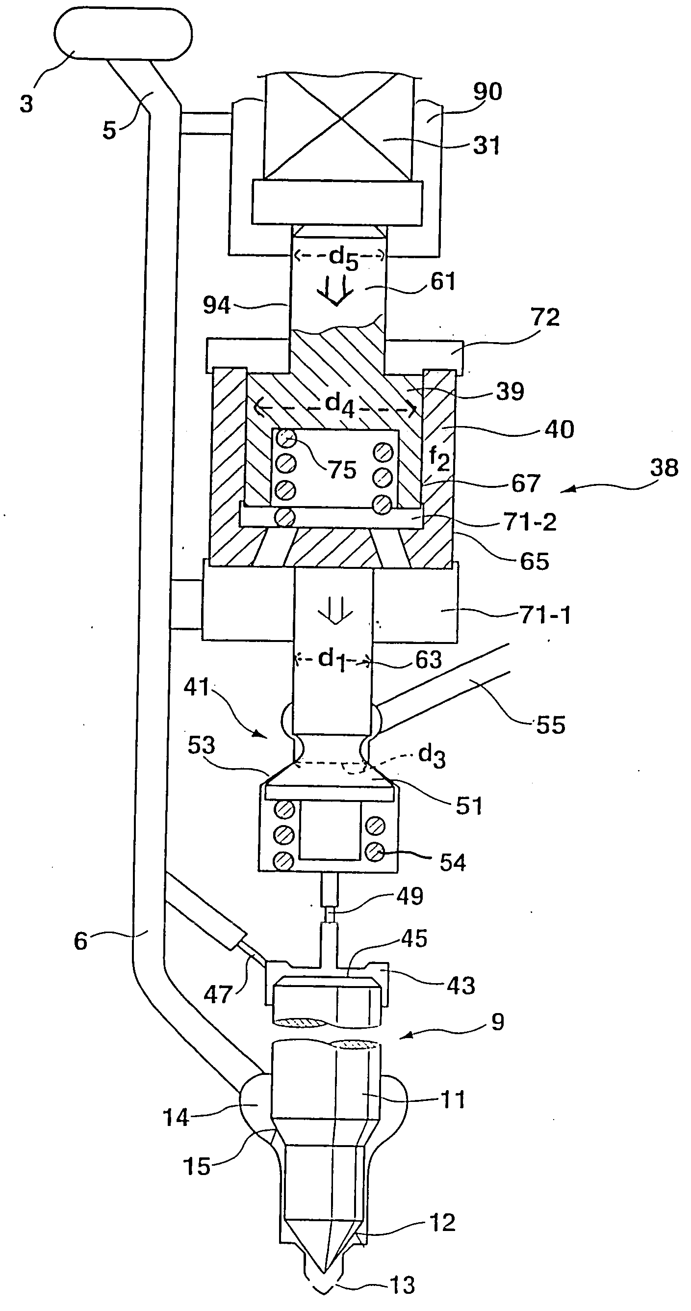
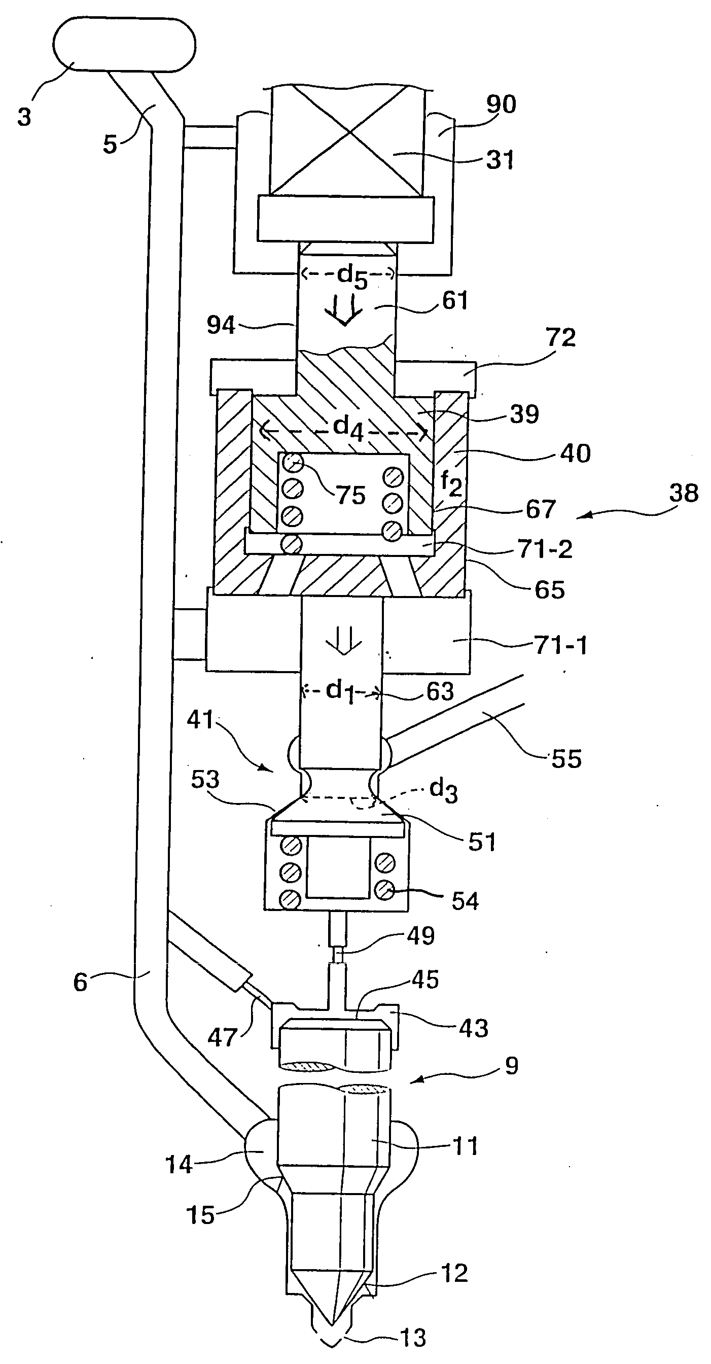
[0005] The fuel injection system 1 of the invention is supplied with fuel at high pressure by a pressure reservoir (common rail) 3 via a high-pressure line 5, from which fuel flows via an injection line 6 to reach an injection valve 9. An internal combustion engine normally has several such injection valves, and for the sake of simplicity only one is shown. The injection valve 9 has a valve needle (valve piston, nozzle needle) 11, which in its closing position, with a conical valve sealing face 12, closes injection openings 13 through which fuel is to be injected into the interior of a combustion chamber of the engine. The fuel reaches the vicinity of the nozzle needle via an annular nozzle chamber 14, from which, via a control face 15 embodied as a pressure shoulder, it makes it possible to exert a pressure in the opening direction of the nozzle needle. When this pressure exerts a force in the opening direction on the valve needle that overcomes forces acting counter to this openin...
PUM
 Abstract
Description
Claims
Application Information