
Method and system for power generation

a power generation and method technology, applied in the field of power generation, can solve the problems of threatening habitats, climate change, and fossil fuels are a non-renewable resource that will, at some point, become harder and harder to obtain, and achieve the effect of increasing the rotational speed of the wheel

Inactive Publication Date: 2007-01-04
ENERGY & ENGINE TECH
View PDF6 Cites 14 Cited by
  • Summary
  • Abstract
  • Description
  • Claims
  • Application Information

AI Technical Summary

Benefits of technology

[0007] The present invention overcomes the problems of fossil-fuel use and the deficiencies of other renewable energy sources by providing a self contained power generating system that combines the power generating capabilities of a magneto flywheel and a turbine system. The magneto flywheel generates an initial level of electricity, capable of starting one or more blowers that can be used to generate high-velocity air pressure. The high velocity air pressure can be directed at a series of turbine fan blades, increasing the power generating levels of the system by increasing the rate at which a shaft of an alternator is turned. The alternator can then provide enough energy not only for the system but can also act as an energy source for external power systems. Because the source of electricity is magnets and air, the source of the electricity is clean, re-usable and is of an unlimited supply.
[0009] Another aspect of the present invention comprises a method of generating electricity, wherein stationary magnets are positioned adjacent to the rotational magnets coupled to the horsepower accelerator wheel in such a way as to induce rotation of the wheel. The wheel drives a shaft coupled to an alternator that generates a first level of electricity. A portion of the first level of electricity can be transmitted to a first blower to generate high-velocity air against a first set of turbine fan blades coupled to the wheel. The operation of the first blower against the first set of turbine blades increases the rotational speed of the wheel, thereby generating a second level of electricity at the alternator that is greater than the first level. A portion of the second level of electricity can be transmitted to the first blower and a second blower, wherein the second blower generates high-velocity air against a second set of turbine fan blades coupled to the wheel. The operation of the first blower and the second blower against the turbine blades further increases the rotational speed of the wheel, thereby generating a third level of electricity at the alternator that is greater than the second level. A portion of the third level of electricity can then be transmitted to external electrical consumers.

Problems solved by technology

As the world's population expands and its economy increases, increased use of fossil fuels has raised atmospheric concentrations of carbon dioxide, threatening habitats and causing climate changes.
While fossil fuels are the basis for many nations′ economies, fossil fuels are a non-renewable resource that will, at some point, become harder and harder to obtain.
While wind, water, and solar power have found limited application in specific areas of the world, none of these provides a cost-efficient power source in all areas of the U.S., much less the world.
Hydro-electric power is only cost efficient in areas where large dams and sufficient water-sources are currently in place.
Solar power cells have never been able to generate enough energy to reach the efficiency or scale many had hoped.
Absent having a power substation next door, most truck-stops are not able to provide sufficient power to the commercial vehicles in order to allow drivers to get the legislated amount of rest in their vehicles, while keeping the vehicle powered at the truck or rest stops.

Method used


Image

  • Method and system for power generation
  • Method and system for power generation
  • Method and system for power generation

Examples


Embodiment Construction

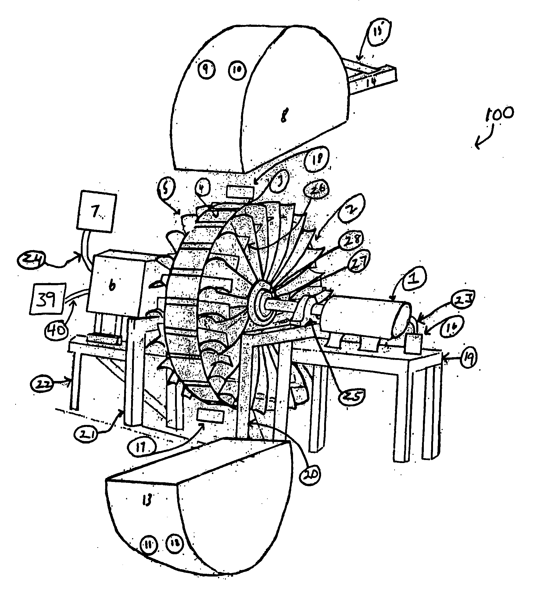
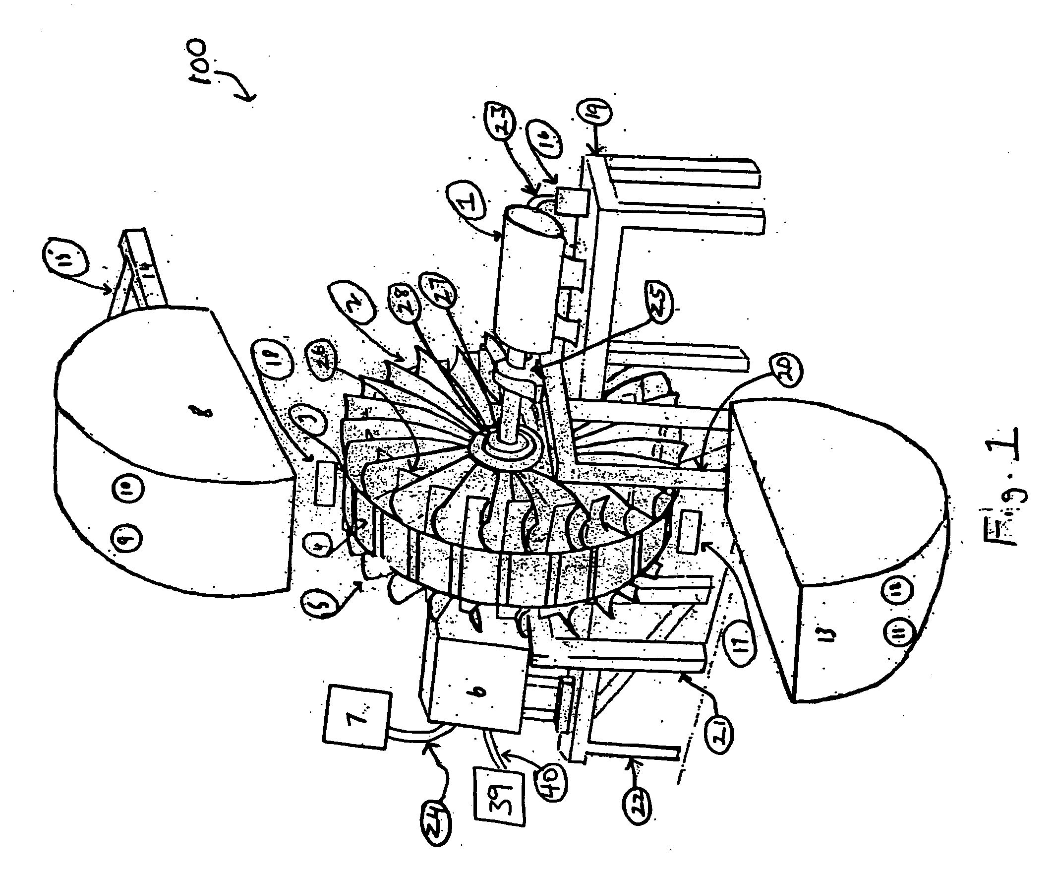
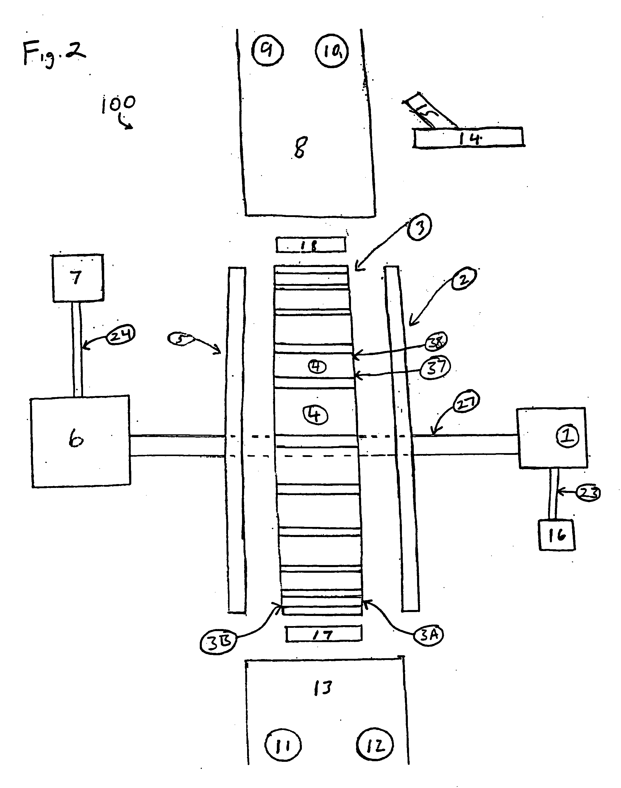
[0014] The present invention supports the generation of electrical power through the use of a horsepower accelerator wheel as can be more readily understood by reference to the representative system illustrated in FIGS. 1 and 2. FIG. 1 is a angled view of an electrical power generation system (“generator system”) 100, in accordance with an exemplary embodiment of the present invention. FIG. 2 is a frontal view of the generator system 100 in accordance with an exemplary embodiment of the present invention. The generator system 100 can include a motor 1 comprising a singe-phase or three-phase motor. The motor 1 can be designed to receive standard American (60 Hz.) or European (50 Hz.) electricity. The size of the motor 1 is generally determined based on the application or amount of power that must be generated by the system, however, any size motor 1 can be used. The motor 1 typically acts as a load balancer for the generator system 100. In one exemplary embodiment, the motor 1 is a 3...


PUM


Abstract

A magneto-turbine power generating system allows for the clean, efficient generation of excess electrical power on a small or large scale. The magneto-turbine power generating system is a self-contained system that generates power greatly in excess of the system's needs, thereby allowing the system to act as an energy source for other products requiring electrical energy. A flywheel combining magnetic and turbine power generating capabilities allows for a clean source of reusable energy. The use of a magneto flywheel provides an electrical generating system capable of starting without need of an extrinsic electrical source. Once the magneto flywheel generates a low-level of electrical power, the turbine system is powered to increase the power generation capabilities of the system.

Description

STATEMENT OF RELATED PATENT APPLICATION [0001] This non-provisional patent application claims priority under 35 U.S.C. §119 to U.S. Provisional Patent Application No. 60 / 582,314, titled Power Generator, filed Jun. 23, 2004. The provisional application is hereby fully incorporated herein by reference.FIELD OF THE INVENTION [0002] The present invention relates to the field of power generation. More particularly, the present invention relates to a system comprising a flywheel magneto generator having turbine fan blades for increased power generation. BACKGROUND OF THE INVENTION [0003] As the world's population expands and its economy increases, increased use of fossil fuels has raised atmospheric concentrations of carbon dioxide, threatening habitats and causing climate changes. Even with improvements in efficiency and environmental protection, some experts say that atmospheric levels of carbon dioxide may be double that of the pre-industrial era by the end of the twenty-first century....

Claims


Application Information

Patent Timeline
Patent Type & Authority Applications(United States)
IPC IPC(8): F03D9/00H02P9/04
CPCF03D3/002Y02E10/74F03G7/10F03D9/12Y02E60/16H02K53/00H02N11/008Y02E70/30
Inventor KILLIAN, DANIEL J.
Owner ENERGY & ENGINE TECH
Learn More