Liquid crystal display apparatus including touch panel
a display apparatus and touch panel technology, applied in the field of liquid crystal display apparatus, can solve the problems of large total thickness including touch panel and display instability, and achieve the effect of reducing thickness including touch panel
- Summary
- Abstract
- Description
- Claims
- Application Information
AI Technical Summary
Benefits of technology
Problems solved by technology
Method used
Image
Examples
first embodiment
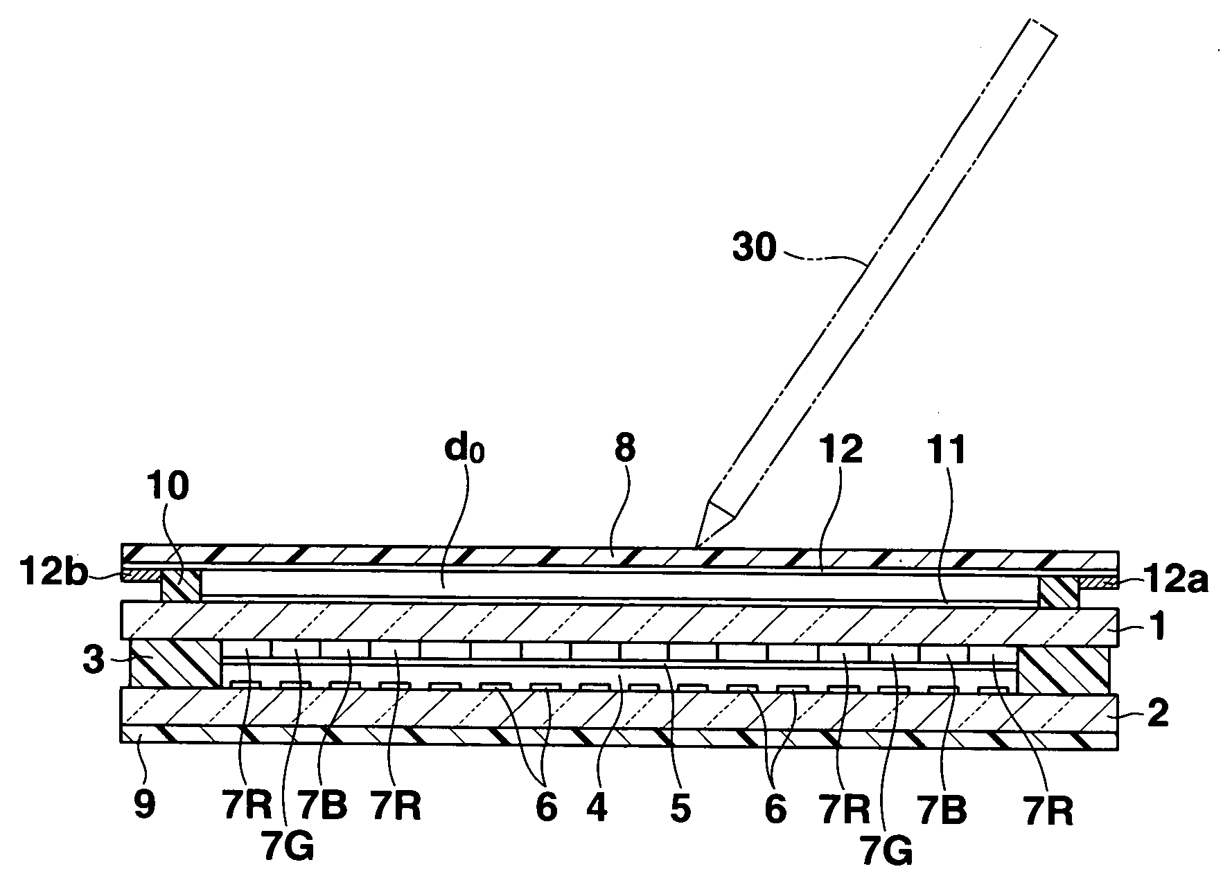
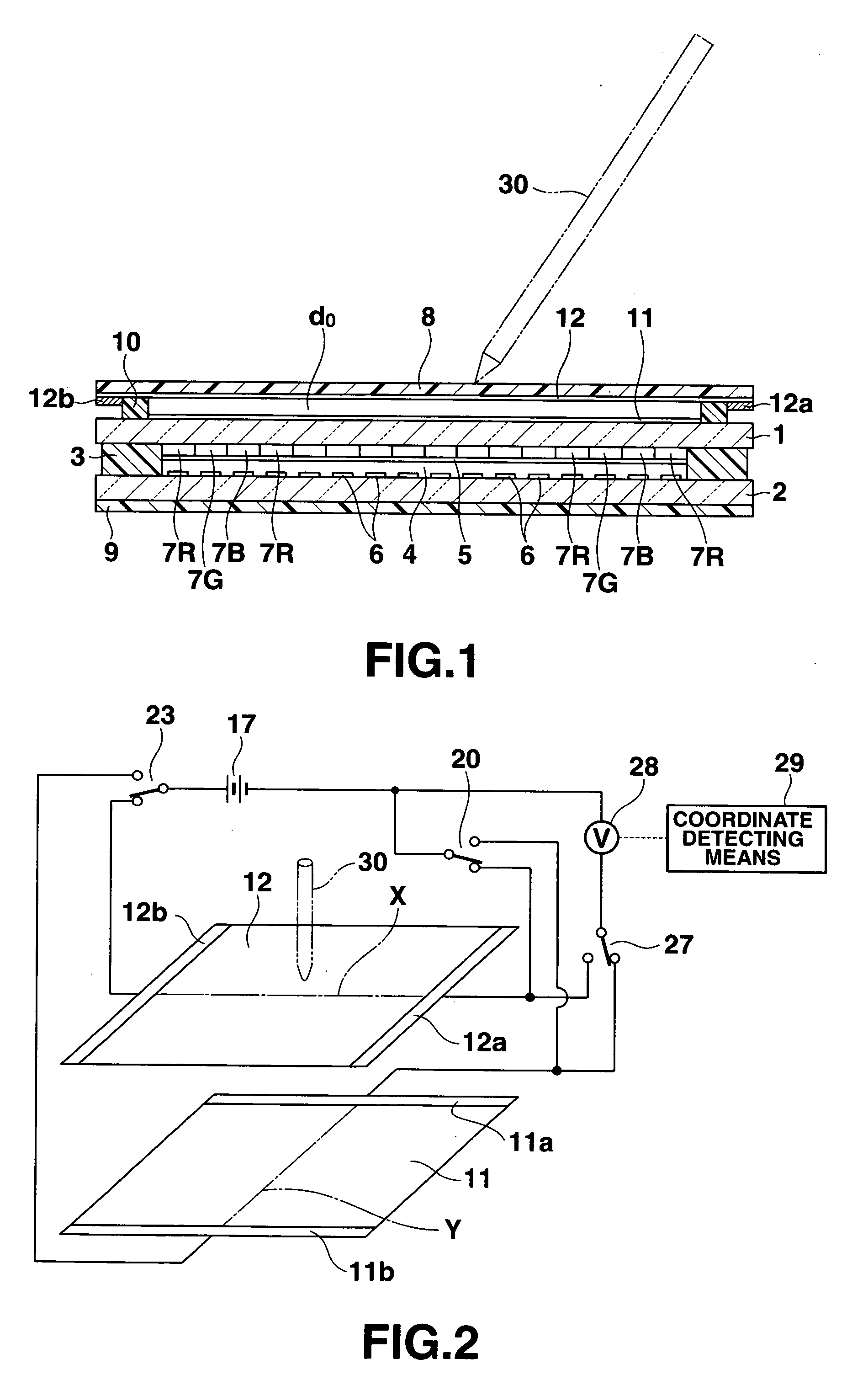
[0082]FIGS. 1 and 2 show a first embodiment of the present invention, wherein FIG. 1 is a cross-sectional view of a liquid crystal display device, and FIG. 2 is a schematic block diagram of touched position coordinate detecting means thereof.
[0083] As shown in FIG. 1, this liquid crystal display device has a pair of transparent substrates 1 and 2 on an observation side (an upper side in the drawing) and an opposite side which are jointed with each other through a frame-like sealing material 3. A liquid crystal layer 4 is sealed in a region surrounded by the sealing material 3 between these substrates 1 and 2. First and second transparent electrodes 5 and 6 which are respectively provided on opposed inner surfaces of the pair of substrates 1 and 2 to face each other and form a plurality of pixel regions in which the alignment state of liquid crystal molecules is controlled by applying an electric field to the liquid crystal layer 4. A pair of observation-side and opposite-side polar...
second embodiment
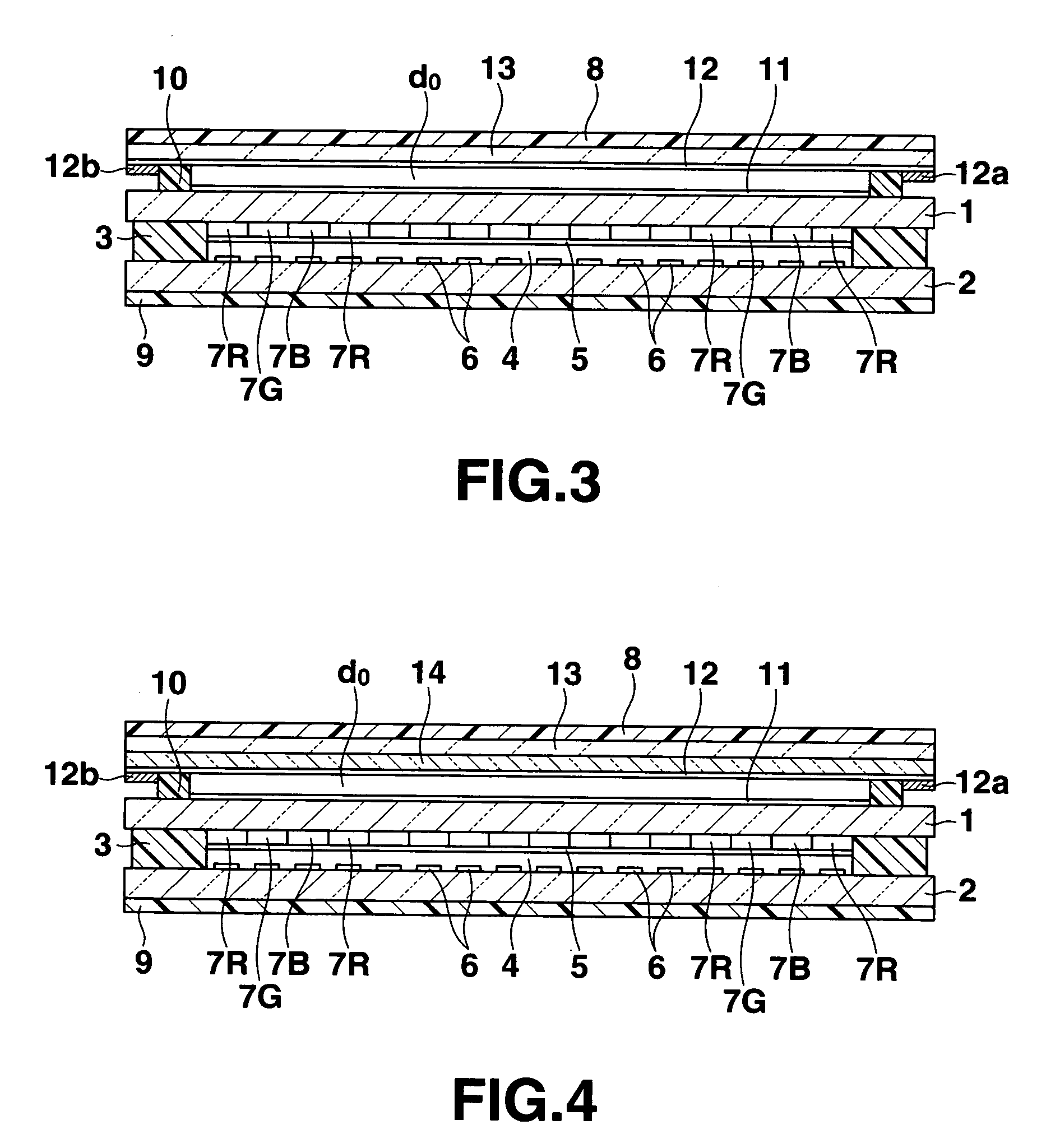
[0102]FIG. 3 is a cross-sectional view showing a liquid crystal display apparatus according to a second embodiment of the present invention. In this embodiment, like reference numerals denote members or parts which are substantially equal to those in the first embodiment, thereby eliminating their explanation.
[0103] According to a liquid crystal display device apparatus of this embodiment, an optical compensation film 13 which compensates display characteristics is arranged on a surface of an observation-side polarizing plate 8 close to an observation-side substrate 1 side, a second electroconductive film 12 is formed on a surface of the optical compensation film 13 close to the observation-side substrate 1 side, and other structures are the same as those in the first embodiment.
[0104] The optical compensation film 13 is formed of one of a contrast compensation film such as a phase plate which improves display contrast, and a discotic liquid crystal film which compensates the view...
third embodiment
[0109]FIG. 4 is a cross-sectional view showing a liquid crystal display device according to a third embodiment of the present invention. In this embodiment, like reference numerals denote constituent parts equal to those in the first and second embodiments, thereby eliminating their explanation.
[0110] According to a liquid crystal display device of this embodiment, an optical compensation film 13 which compensates display characteristics and an optically isotropic transparent film 14 are sequentially provided on a surface of an observation-side polarizing plate 8 on an observation-side substrate 1 side, a second electroconductive film 12 is formed on a surface of the transparent film 14, and other structures are the same as those in the first embodiment.
[0111] According to this liquid crystal display device, since the optical compensation film 13 and the transparent film 14 are laminated on the inner surface of the observation-side polarizing plate 8 and the second electroconducti...
PUM
| Property | Measurement | Unit |
|---|---|---|
| angle | aaaaa | aaaaa |
| thickness | aaaaa | aaaaa |
| angle | aaaaa | aaaaa |
Abstract
Description
Claims
Application Information
 - R&D
- Intellectual Property
- Life Sciences
- Materials
- Tech Scout
- Unparalleled Data Quality
- Higher Quality Content
- 60% Fewer Hallucinations
Browse by: Latest US Patents, China's latest patents, Technical Efficacy Thesaurus, Application Domain, Technology Topic, Popular Technical Reports.
© 2025 PatSnap. All rights reserved.Legal|Privacy policy|Modern Slavery Act Transparency Statement|Sitemap|About US| Contact US: help@patsnap.com


