Metal reflector and process for producing it

Inactive Publication Date: 2007-01-04
AUER LIGHTING
View PDF15 Cites 6 Cited by
  • Summary
  • Abstract
  • Description
  • Claims
  • Application Information

AI Technical Summary

Benefits of technology

[0011] By contrast, the invention is based on the object of providing a reflector with good optical properties. A further object of the invention is to provide a reflector which is not sensitive to high temperatures and allows good dissipation of heat which is generated. Another object of the invention is to provide a combination of metal reflector and co

Problems solved by technology

In this case, the geometry produced by the deep-drawing operation cannot be anything lik

Method used


Image

  • Metal reflector and process for producing it
  • Metal reflector and process for producing it
  • Metal reflector and process for producing it

Examples


Example

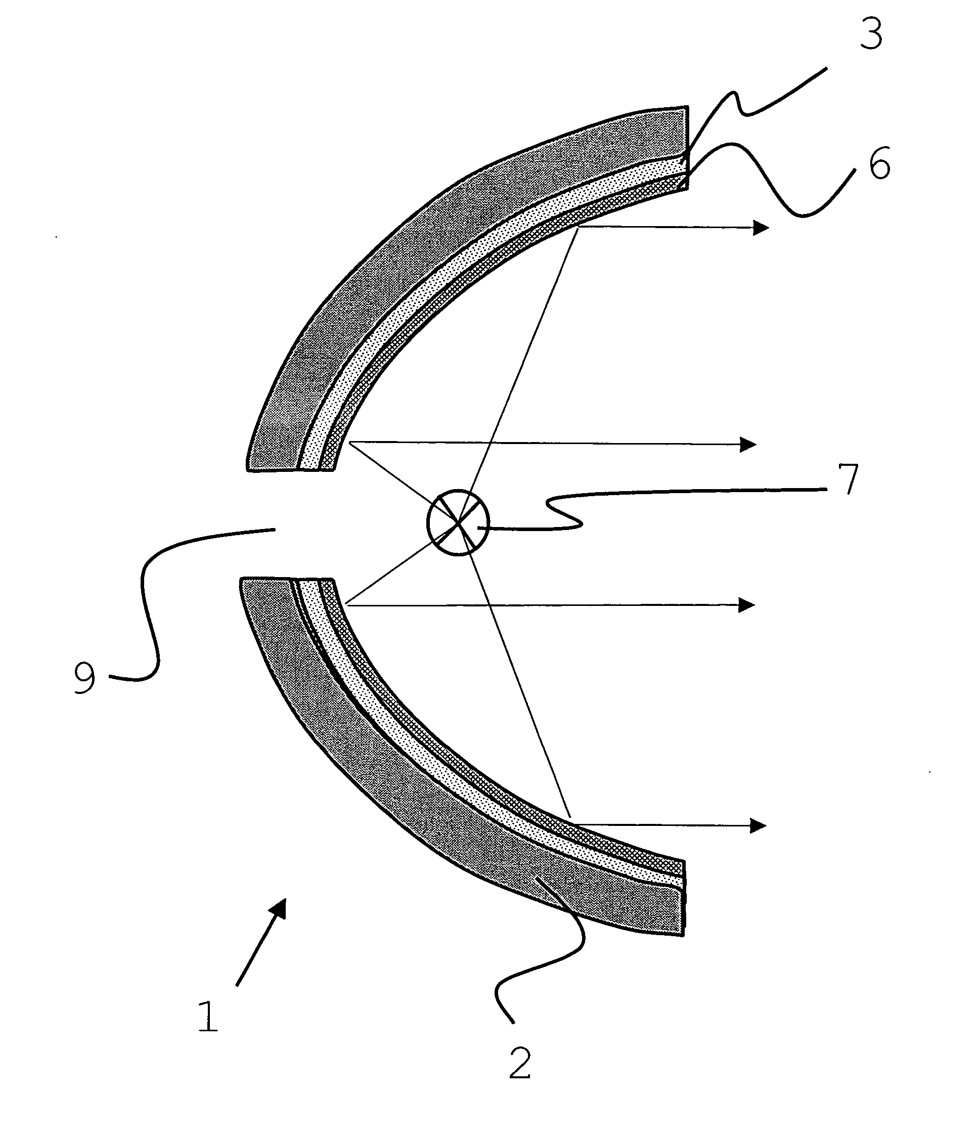
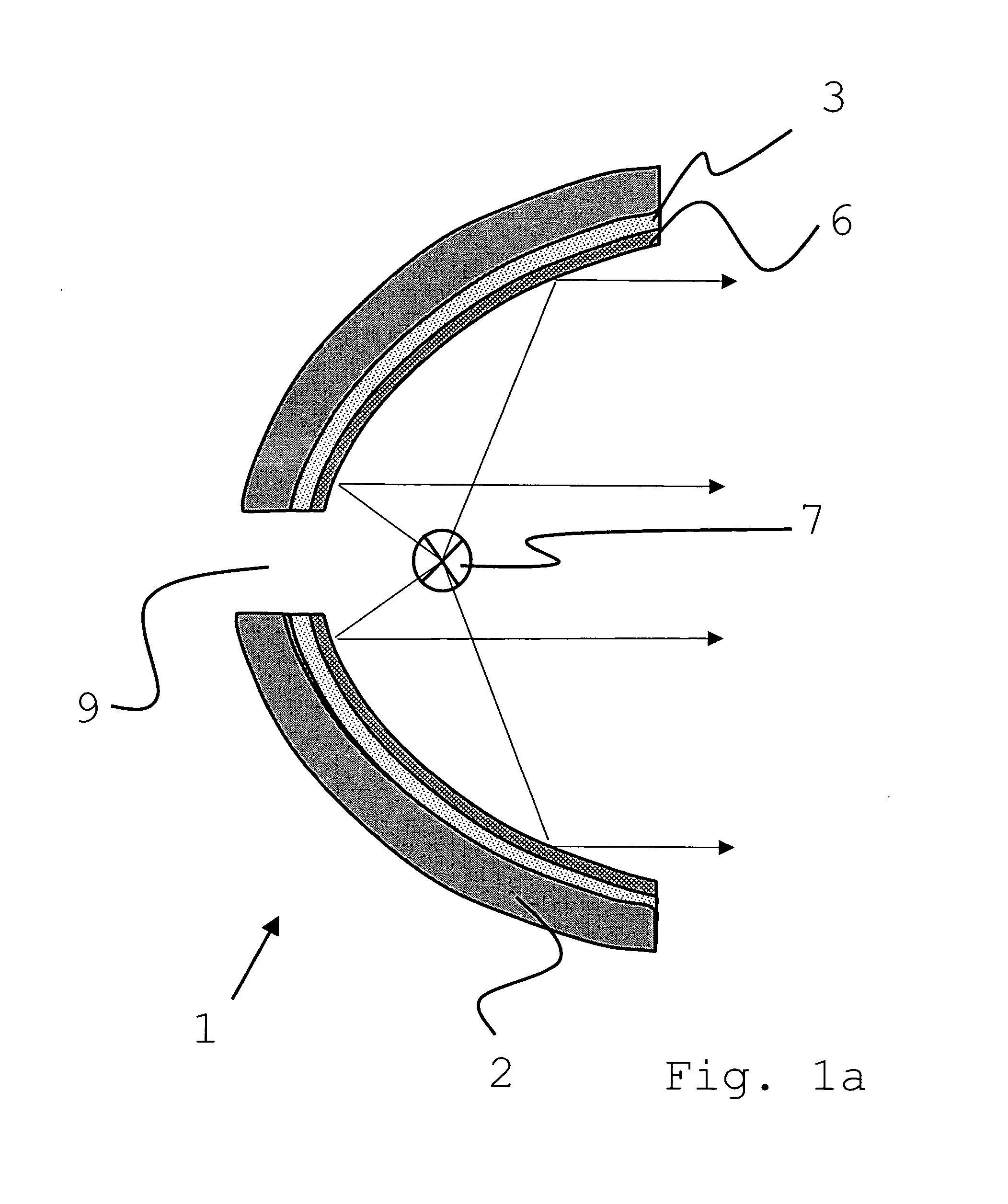
[0078]FIGS. 1a to 1f show a diagrammatic sectional view of a reflector 1 according to the invention in various embodiments of the applied coating. The reflector is produced from a metal block by means of a chip-forming process and accordingly has a thick-walled metal substrate 2. The reflector geometry is substantially parabolic. The reflector 1 has a concentric cutout 9, through which a luminous means can be introduced.

[0079] According to the exemplary embodiment shown in FIG. 1a, the metal substrate 2 is provided with a silver or aluminum reflection layer 3 and a protective layer 6 in the form of a single layer, for example of SiO2. A light source 7 is diagrammatically indicated in the center of the reflector.

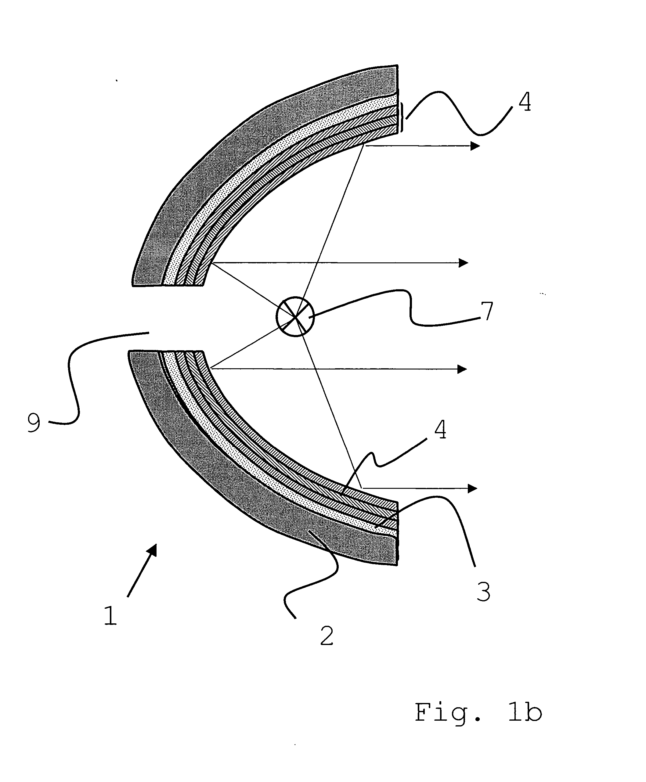
[0080] In accordance with the exemplary embodiment shown in FIG. 1b, the metal substrate 2 is provided with a silver or aluminum reflection layer 3 and with an alternating layer 4. In this exemplary embodiment, the alternating layer 4 comprises a total of three titanium oxi...


PUM

PropertyMeasurementUnit
Lengthaaaaaaaaaa
Lengthaaaaaaaaaa
Lengthaaaaaaaaaa

Abstract

The invention relates to a process for producing a high-precision reflector and its coating. A reflector is produced from a solid material using a material-removing process and is coated with a cold-light mirror layer.

Description

CROSS-REFERENCE TO RELATED APPLICATIONS [0001] This application claims the benefit under 35 U.S.C. §119 of German Application No. 10 2005 028 456.6, filed on Jun. 17, 2005, the entire contents of which are incorporated by reference herein. BACKGROUND OF THE INVENTION [0002] 1. Field of the Invention [0003] The invention relates to a process for producing a high-precision metal reflector and to a metal reflector. A projection system also forms the subject matter of the invention. [0004] 2. Description of Related Art [0005] In practice, reflectors have a wide range of applications; mention may be made in particular of headlamp reflectors, in particular in the automotive industry, and of reflectors as used for projection systems, for example digital projectors. [0006] DE 100 29 905 describes a reflector for a motor vehicle, in which a cold-light coating has been applied by means of a deposition process. The reflector has a base body made from plastic. [0007] Plastic reflectors of this ...

Claims


Application Information

Patent Timeline
IPC IPC(8): H01S3/081F21V29/505
CPCC23C30/00F21S48/1394F21V7/22G02B5/0816G02B5/10F21V29/505C23C28/34C23C28/345C23C28/3455C23C28/42C23C28/322F21S41/37F21V7/24F21V7/28
Inventor MEHRTENS, ANDREEKUEPPER, THOMASZOGG, LUTZ
Owner AUER LIGHTING
Why Eureka
Try Eureka