
Independent personal underwater navigation system for scuba divers

Inactive Publication Date: 2007-01-11
SCUBA NAV
View PDF6 Cites 52 Cited by
  • Summary
  • Abstract
  • Description
  • Claims
  • Application Information

AI Technical Summary

Benefits of technology

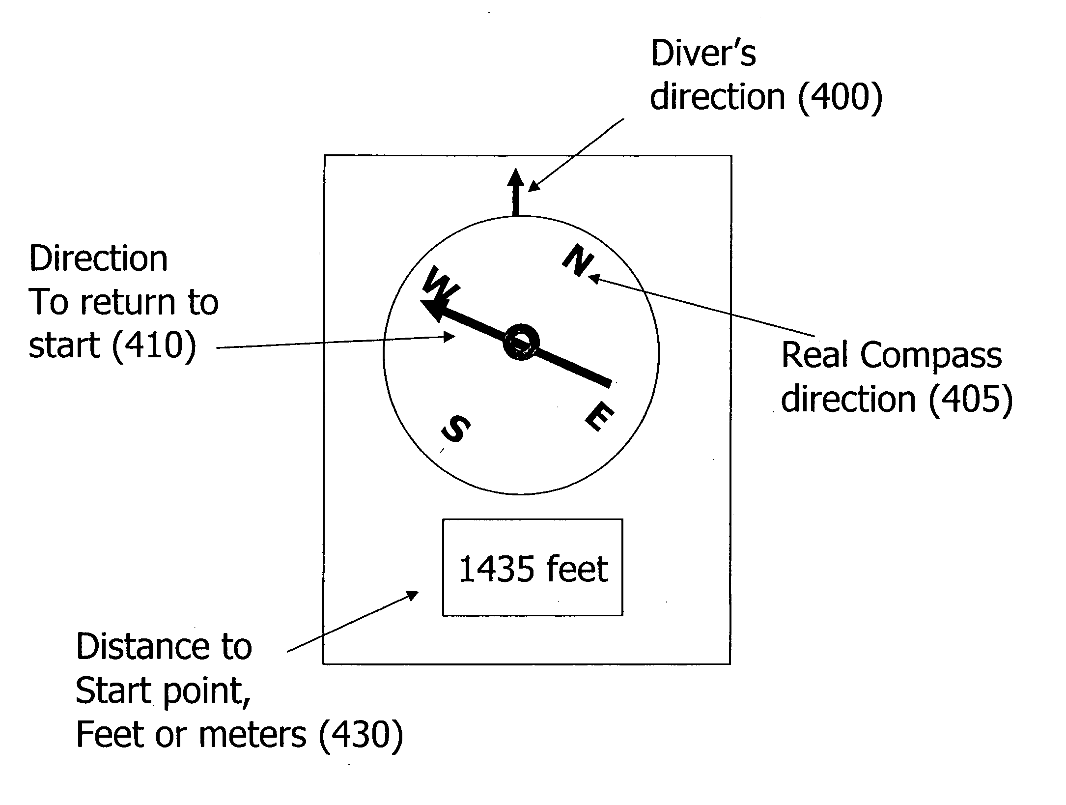
[0021] A more effective personal dive navigation system would significantly enhance the enjoyment of the scuba diving experience by removing the anxiety of correct navigation. These include concerns that getting too far away from the boat resulting in disorientation, a return swim that may be beyond the diver's capabilities, or a dive that takes longer than a scheduled dive time where the air supply may become depleted.
[0022] By effectively replacing a personal experienced dive site guide, a navigation system would ideally always let a diver know how far and in what direction the boat is located from their current position. This would enable the diver to explore on random paths led by interesting viewing, rather than navigation concerns. The overall result would be a much more pleasurable dive.
[0026] By providing accurate navigation information, this kind of situation can be avoided, both enhancing safety as well as improving the experience by reducing anxiety. Feature Summary of the Present Invention

Problems solved by technology

All divers, novice through experienced, face challenges when navigating underwater.
As simple and limited as this is, even this skill is difficult for many divers to master, and a typical diver may never use this technique after passing the skills test.
Even if performed properly, the compass-based navigation technique leaves much to be desired.
First, it does not take into account underwater currents which can be both strong and invisible making it very difficult for a diver to estimate the error introduced much less compensate for this.
Second it does not account for non-straight-line paths which may be either necessary to circumnavigate obstacles, or may just be desirable to enjoy viewing features that are off the chosen path, in caves and channels, etc.
This situation is only aggravated by many typical dive sites with less than optimal visibility.
Abandoning the compass can be very disorienting since many dive sites are mixtures of coral heads, sand beds, and other features which are very similar to each other over a wide area making landmark recognition and tracking problematic.
All of these products attempt to address the issues described above but fall short in fully enabling a diver to explore as if they had a true dive guide along.
They typically have limited range either from the start point, or from the surface of the water.
In addition they can suffer from common situations where their accuracy and even their basic functions can be compromised.
Thus any objects or thermoclines in the path cause signal to be lost.
In addition, such systems are typically limited to a range of about 300 meters or so.
Without someone remaining on shore to monitor the beacon, it is susceptible to being moved or even being stolen.
However, these suffer from several disadvantages in the underwater environment.
This severely limits travel depth and mobility during a dive.
Recreational dive safety limits support dive depths of greater than one hundred twenty feet so that divers using these devices are limited to only relatively shallow dives.
In addition, by tying the diver to a surface line the freedom that is provided by SCUBA (Self Contained Underwater Breathing Apparatus) is compromised.
Mobility to travel through wrecks, coral heads and any features which do not provide a direct line path to the surface becomes problematic.
The device which should provide enhanced safety and enjoyment may itself become a safety hazard by increasing the probability that a diver may become entangled by the surface line.

Method used


Image

  • Independent personal underwater navigation system for scuba divers
  • Independent personal underwater navigation system for scuba divers
  • Independent personal underwater navigation system for scuba divers

Examples


Embodiment Construction

[0034] A description of preferred embodiments of the invention follows.

[0035] Overview

[0036] Recent developments and advances in Micro Electro-Mechanical Systems (MEMS) components as well as continuing improvements in the cost, performance and power of microcomputing devices have enabled the miniaturization and cost reduction of an Inertial Navigation System (INS) to the point that it is practical to implement a personal system for use by SCUBA divers and other water sport enthusiasts. This novel approach requires innovation in overcoming the inaccuracies in these devices which will then make it a solution to the navigation problem currently addressed by less effective means.

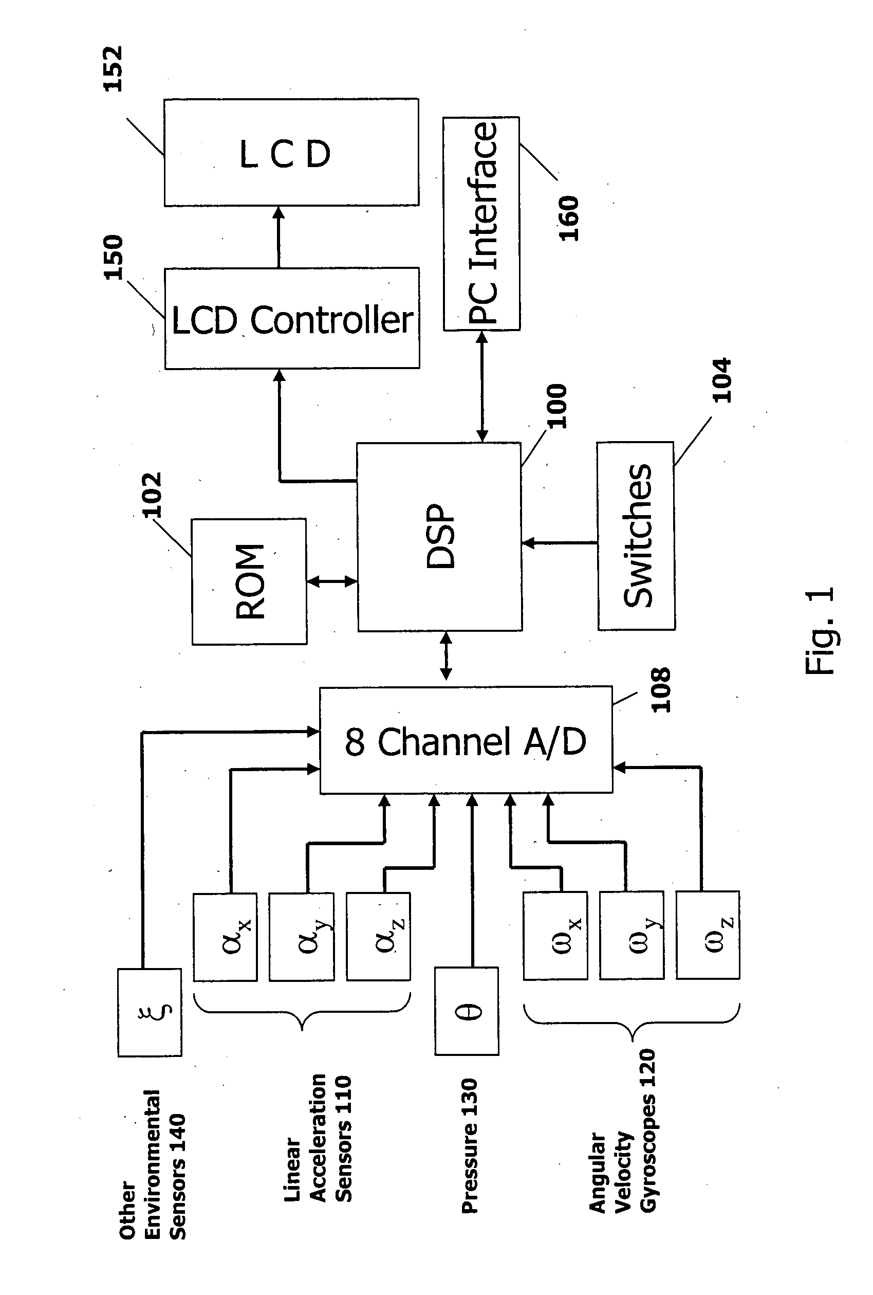
[0037]FIG. 1 is high level block diagram of the hardware components of a personal underwater INS according to one possible embodiment of the present invention. The system includes a Digital Signal Processor (DSP) 100, a Read Only Memory (ROM) 102, switches 104, a multi-channel analog to digital converter (A / D...


PUM


Abstract

An underwater personal Inertial Navigation System (INS) that uses linear acceleration and angular velocity sensors to fix the position of a diver in relation to a reference point. The sensor inputs are corrected by other sensors such as pressure or magnetic sensors.

Description

RELATED APPLICATION(S) [0001] This application claims the benefit of U.S. Provisional Application No. 60 / 681,425, filed on May 16, 2005. The entire teachings of the above application(s) are incorporated herein by reference.BACKGROUND OF THE INVENTION [0002] This application relates to an underwater personal navigation system, such as may be used by SCUBA divers. Introduction to Dive Navigation [0003] All divers, novice through experienced, face challenges when navigating underwater. Open water diver certification programs include instruction on basic navigation skills for use on dive activities. This is generally limited to instruction on how to read a compass underwater, followed by directions on how to swim in a fixed direction for a fixed time, and then reversing the direction for a similar time to return to a start location. [0004] As simple and limited as this is, even this skill is difficult for many divers to master, and a typical diver may never use this technique after pas...

Claims


Application Information

Patent Timeline
IPC IPC(8): G01C17/00
CPCG01C21/165G01C17/00G01C21/1654
Inventor BAUCH, AARON
Owner SCUBA NAV
Learn More