Composite material and light emitting element, light emitting device, and electronic device using the composite material

a technology of composite materials and light emitting elements, applied in the field of composite materials, can solve the problems of insufficient technical development to achieve the effect of longer life, difficult to obtain characteristics, and insufficient one, and achieve the effect of low power

Active Publication Date: 2007-01-11
SEMICON ENERGY LAB CO LTD
View PDF41 Cites 42 Cited by
  • Summary
  • Abstract
  • Description
  • Claims
  • Application Information

AI Technical Summary

Benefits of technology

[0027] In addition, another feature of the present invention is that the organic compound is a high molecular compound.
[0037] By applying the composite material of the present invention to a light emitting device, a light emitting device consuming low power can be obtained.

Problems solved by technology

This characteristic is difficult to be obtained by a point light source typified by an incandescent lamp or an LED or a line light source typified by a fluorescent lamp.
However, in order to extend the lifetime, a means described in Patent Document 1 is insufficient and technical development to achieve the longer lifetime has been required.

Method used


Image

  • Composite material and light emitting element, light emitting device, and electronic device using the composite material
  • Composite material and light emitting element, light emitting device, and electronic device using the composite material
  • Composite material and light emitting element, light emitting device, and electronic device using the composite material

Examples


embodiment mode 1

[0107] A composite material of the present invention has a feature of including metal oxide and an organic compound having an oxidation peak potential with respect to an Ag / Ag+ electrode in dimethylformamide (DMF) at room temperature within the range of 0 V or more and 1.5 V or less (vs. Ag / Ag+), preferably 0.2 V or more and 1.1 V or less (vs. Ag / Ag+). In addition, a composite material of the present invention has a feature of including metal oxide and an organic compound having an oxidation peak potential with respect to an oxidation-reduction potential of ferrocene in dimethylformamide (DMF) at room temperature within the range of 0 V or more and 1.5 V or less (vs. Fc / Fc+), preferably 0.1 V or more and 1.0 V or less (vs. Fc / Fc+). Further, a composite material of the present invention has a feature of including metal oxide and an organic compound having ionization potential in dimethylformamide (DMF) solution at room temperature is 4.8 eV or more and 6.4 eV or less, preferably 5.0 ...

embodiment mode 2

[0121] A light emitting element of the present invention has a plurality of layers between a pair of electrodes. The plurality of layers are stacked by combining a layer made of a substance having a high carrier injecting property or having a high carrier transporting property so that a light emitting region is formed in a position separated from an electrode, in other words, so that carriers are recombined in a site separated from an electrode.

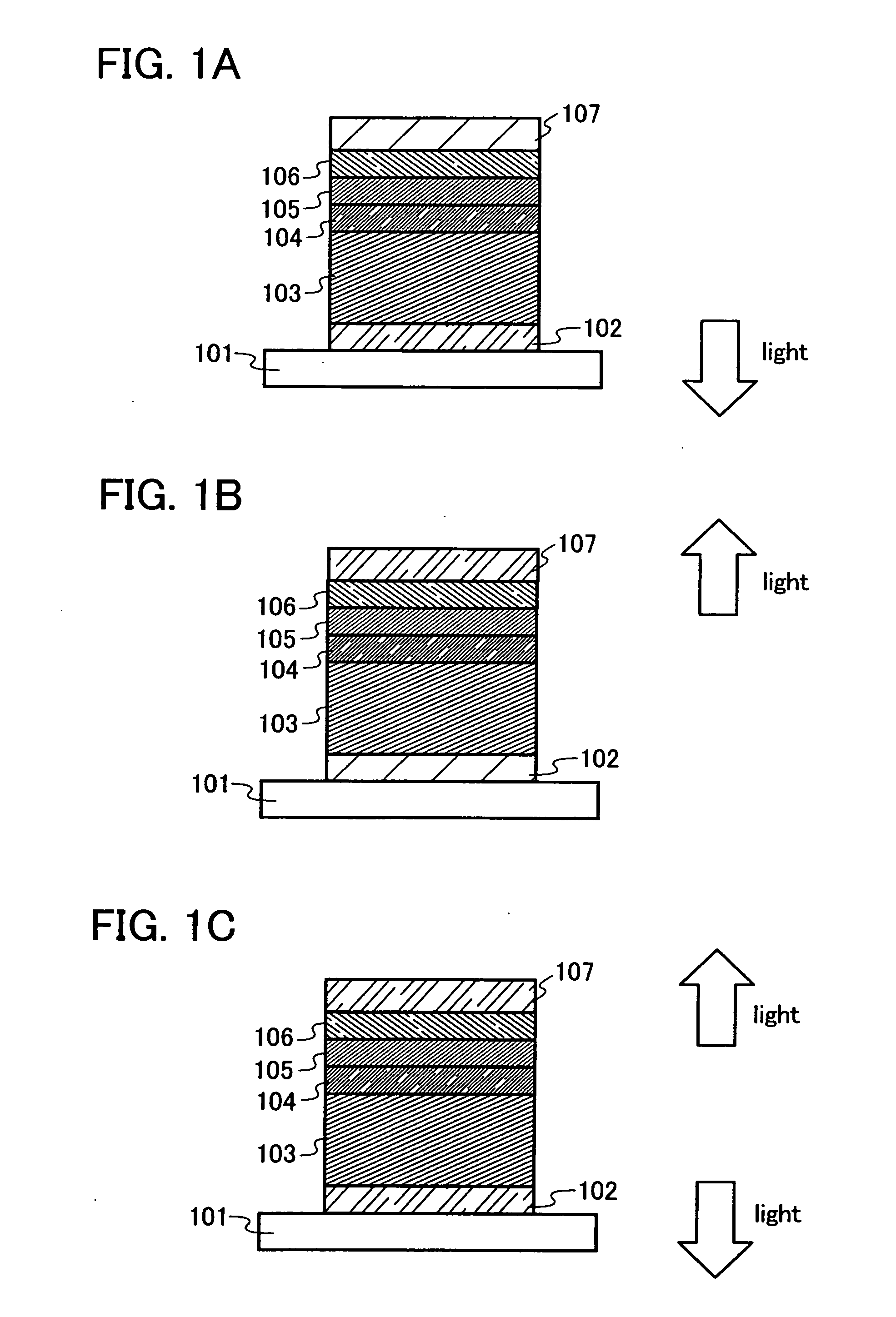
[0122] One mode of the light emitting element of the present invention will be explained with reference to FIG. 1A.

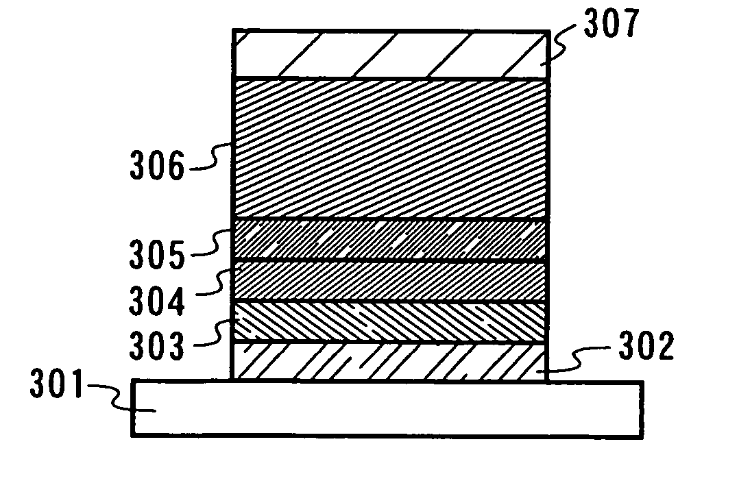
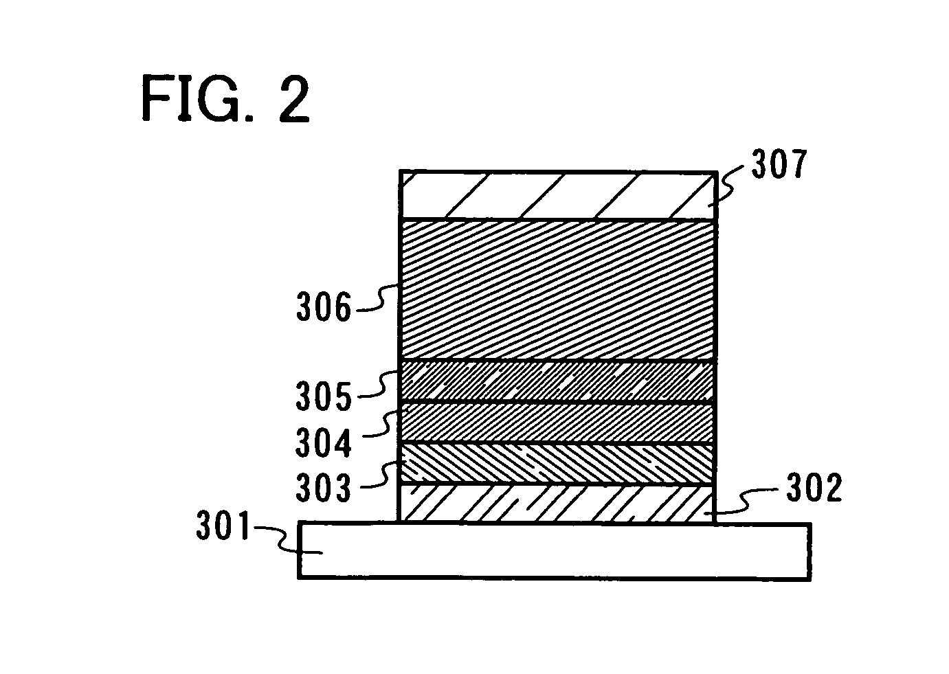
[0123] In this embodiment mode, the light emitting element is formed by a first electrode 102; a first layer 103, a second layer 104, a third layer 105, and a fourth layer 106 which are sequentially stacked over the first electrode 102; and a second electrode 107 provided thereover. It is to be noted that explanation will be made with the assumption that the first electrode 102 serves as an anode and the second electrode 107 se...

embodiment mode 3

[0144] In this embodiment mode, a light emitting element having a different structure from a structure described in Embodiment Mode 2 will be explained with reference to FIGS. 5A to 5C and FIGS. 6A to 6C. In the structure described in this embodiment mode, a layer including a composite material of the present invention can be provided so as to be in contact with an electrode serving as a cathode.

[0145]FIG. 5A shows an example of a structure of a light emitting element of the present invention. The light emitting element has a structure in which a first layer 411, a second layer 412, and a third layer 413 are stacked between a first electrode 401 and a second electrode 402. In this embodiment mode, a case where the first electrode 401 serves as an anode and the second electrode 402 serves as a cathode will be explained.

[0146] A structure which is the same as Embodiment Mode 2 can be applied to the first electrode 401 and the second electrode 402. The first layer 411 is a layer incl...


PUM

PropertyMeasurementUnit
oxidation-reduction potentialaaaaaaaaaa

Abstract

The present invention provides a composite material in which an organic compound and an inorganic compound are composited, which is superior in conductivity, a composite material which is superior in a property of injecting carriers to an organic compound, and a composite material having low resistance with metal. Further, the present invention provides a light emitting element operating at a low drive voltage by applying the composite material to a current excitation type light emitting element, and a light emitting device consuming low power by manufacturing a light emitting device using the light emitting element. The present invention provides a composite material including metal oxide and an organic compound having an oxidation peak potential with respect to an oxidation-reduction potential of ferrocene in dimethylformamide (DMF) at room temperature within the range of 0 V and 1.5 V (vs. Fc / Fc+), preferably within the range of 0.1 V and 1.0 V (vs. Fc / Fc+).

Description

BACKGROUND OF THE PRESENT INVENTION [0001] 1. Field of the Present Invention [0002] The present invention relates to a composite material in which an organic compound and inorganic compound are composited and which is superior in a carrier transporting property and a property of injecting carriers to an organic compound. Moreover, the present invention relates to a current excitation type light emitting element using the composite material. In addition, the present invention relates to a light emitting device and an electronic device having the light emitting element. [0003] 2. Description of the Related Art [0004] In recent years, a light emitting element using an organic compound having a light emitting property has been actively researched and developed. These light emitting elements basically have a structure in which a layer including an organic compound having a light emitting property is interposed between a pair of electrodes. By applying voltage to this element, electrons a...

Claims


Application Information

Patent Timeline
Patent Type & Authority Applications(United States)
IPC IPC(8): H01L29/08
CPCH01L27/3209H01L51/0061H01L51/5278H01L51/5088H01L51/0072H10K59/32H10K85/636H10K85/6572H10K50/17H10K50/19
Inventor SEO, SATOSHIKOJIMA, KUMI
Owner SEMICON ENERGY LAB CO LTD
Why Eureka
Try Eureka