Optical image display system and image display unit

a technology which is applied in the field of optical image display system and image display unit, can solve the problems of difficult or complicated plate fabrication, and achieve the effect of large exit pupil and simple structur

Inactive Publication Date: 2007-01-11
NIKON CORP
View PDF3 Cites 151 Cited by
  • Summary
  • Abstract
  • Description
  • Claims
  • Application Information

AI Technical Summary

Benefits of technology

[0008] In view of solving the above problem, one object of the present invention is to provide an optical-image display system and an image-display unit of which the plate has a simple structure but still provides a large exit pupil.
[0018] Any of the embodiments can provide an optical-image display system and an image-display unit that are of simple structure while providing a large exit pupil.

Problems solved by technology

However, this optical-image system poses a problem in that it is difficult or complicated to fabricate the plate.

Method used


Image

  • Optical image display system and image display unit
  • Optical image display system and image display unit
  • Optical image display system and image display unit

Examples


first embodiment

[0066] A first embodiment of the invention is described with reference to FIGS. 1-8. This embodiment pertains to an eyeglass display.

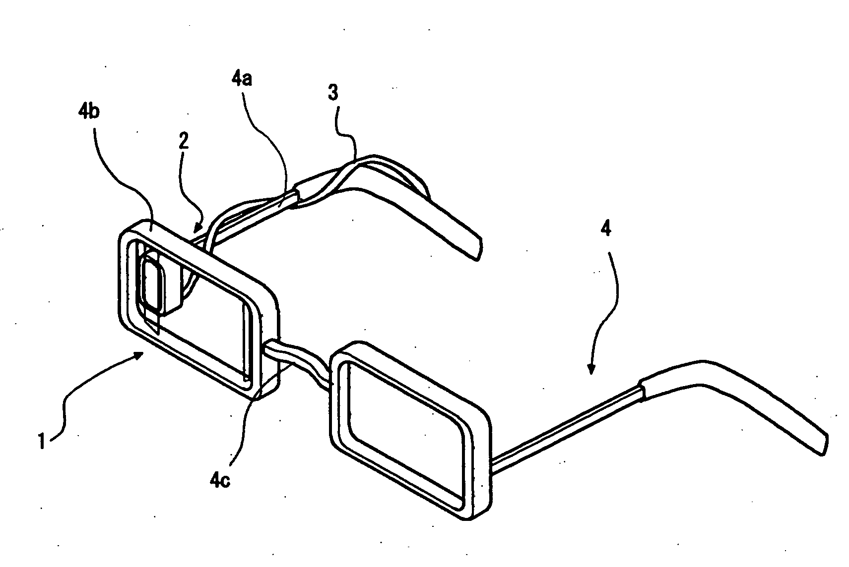
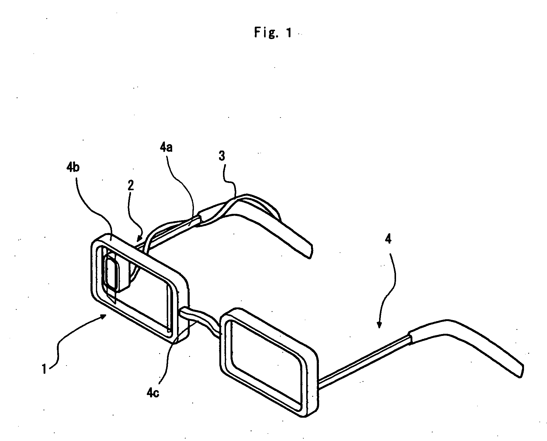
[0067] First, the configuration of the eyeglass display is described. As shown in FIG. 1, the eyeglass display includes an optical-image display system 1, an image-introduction unit 2, and a cable 3. The optical-image display system 1 and the image-introduction unit 2 are supported by a support member 4 (including temples 4a, a rim 4b, and a bridge 4c). The support member 4 is similar to a frame for eyeglasses that is mountable to the head of an observer.

[0068] The optical-image display system 1 has an outer shape similar to an eyeglass lens and is supported by the surrounding rim 4b. The image-introduction unit 2 is supported by the temple 4a. The image-introduction unit 2 is supplied with an image signal and power from an external apparatus by way of the cable 3.

[0069] As mounted, the optical-image display system 1 is situated frontward from one o...

second embodiment

[0129] A second embodiment is described below in reference to FIGS. 10 and 11. This embodiment is directed to an eyeglass display, of which only the point of difference from the first embodiment is described. The point of difference is that the return-reflective surface 11b of the first embodiment is omitted, and a multi-mirror 12a′ is provided in place of the multi-mirror 12a. As shown in FIG. 10(a), the multi-mirror 12a′ is disposed on the surface 12-2 on the observer side of the plate 12, similar to the multi-mirror 12a in the first embodiment. The multi-mirror 12a′ corresponds to the multi-mirror 12a, except that the second reflective-transmissive surface 12a-2′ is omitted and the second reflective-transmissive surfaces 12a-2 are arranged densely in the manner shown in the enlargement of FIG. 10(b). Since the return-reflective surface 11b is omitted, the light flux L from the display is not reciprocated inside the plate 11. But, the forwardly propagating light flux L from the di...

modified second embodiment

[0131] In the second embodiment, two kinds of brightness unevenness can remain in the light flux L as incident on the exit pupil E. First, since the light flux L is not reciprocated inside the plate 11, brightness unevenness is exhibited in the units of light flux L incident on the exit pupil E. Second, as shown in the enlarged view of FIG. 11, a region B is located on the second reflective-transmissive surface 12a-2. The region B has substantially half the size of the corresponding first reflective-transmissive surface 12a-1 and is located remotely to the first reflective-transmissive surface 12a-1. The region B is shaded by the second reflective-transmissive surface 12a-2 adjacent thereto on the right side as seen from the observer. As a result of this shading, the amount of the light flux L reaching the region B is smaller than the amount of light reaching the region A. Hence, the amount of the light flux L directed from the region B to the exit pupil E is smaller than the amount...


PUM


Abstract

Optical-image display systems are disclosed having simple structure and a large exit pupil. An exemplary system includes a transmissive plate having inside an optical path of light flux from a display at each angular field of view of an image-display element. The light flux is internally reflected repeatedly in the transmissive plate. An optical-deflection member is provided in close contact with a predetermined region of one surface of the plate used for internal reflection. The optical-deflection member emits to the outside of the plate a portion of each of the light fluxes from the display having reached the predetermined region, and deflects a portion of each light flux in a predetermined direction by reflection. Thus, a virtual image is formed of the display screen of the image-display element.

Description

CROSS REFERENCE TO RELATED APPLICATIONS [0001] This application is a continuation application of International Application PCT / JP 2005 / 001963, filed Feb. 9, 2005, designating the U.S., which claims the benefit of priority from Japanese Patent Application No. 2004-071511, filed on Mar. 12, 2004, and No. 2004-230528, filed on Aug. 6, 2004, the entire contents of which are incorporated herein by reference. BACKGROUND [0002] 1. Field [0003] The present invention relates to an optical-image display system and an image-display unit mounted to an optical apparatus such as an eyeglass display, a head-mount display, a camera, a portable telephone, a binocular, a microscope, a telescope for forming a virtual image of a display screen of a liquid crystal display, or the like, frontward of an observing eye. [0004] 2. Description of Related Art [0005] In recent years, an optical-image display system having a large exit pupil has been proposed (see Japan Unexamined Patent Application Publication ...

Claims


Application Information

Patent Timeline
Patent Type & Authority Applications(United States)
IPC IPC(8): G02B27/14G02B5/30G02B25/00G02B27/00G02B27/01G02B27/02H04N5/64H04N5/74
CPCG02B27/0081G02B27/0172H04N5/7491G02B2027/0178G02B2027/0125
Inventor HIRAYAMA, YOSHIKAZU
Owner NIKON CORP
Why Eureka
Try Eureka