Method and system for indoor geolocation using an impulse response fingerprinting technique

a fingerprinting and impulse response technology, applied in the direction of navigation instruments, dc level restoring means or bias distorting correction, instruments, etc., can solve the problems of inadequacies of existing radio channel models developed for telecommunications, inability to meet the needs of indoor radio channels, and inability to provide parametric geolocation techniques (and combinations thereof) to provide only limited location accuracy

Active Publication Date: 2007-01-11
INSTITUT NATIONAL DE LA RECHERCHE SCIENTIFIQUE +1
View PDF0 Cites 59 Cited by
  • Summary
  • Abstract
  • Description
  • Claims
  • Application Information

AI Technical Summary

Benefits of technology

[0033] There is also provided a method for training an artificial neural network for predicting a location of a transmitter in an indoor zone of interest where the network is comprised of a plurality of weights and biases. The method comprises the steps of co

Problems solved by technology

One problem of growing importance in indoor environments is the location of people, mobile terminals and equipment.
Indoor radio channels suffer from extremely serious multipath and non-line of sight (NLOS) conditions that have to be modelled and analysed to enable the design of radio equipment for geolocation applications.
Since telecommunication and geolocation applications have different objectives, existing radio channel models developed for telecommunications are not appropriate, and different models and techniques have had to be developed to provide adequate and accurate localisation.
In indoor environments where signal propagation is very complex, these existing parametric geolocation techniques (and combinations thereof) provide only limited location accuracy, as they depend largely on Line of Sight (LOS) to ensure accuracy, an element which of course is largely not present in indoor environments.
The major errors in measure

Method used


Image

  • Method and system for indoor geolocation using an impulse response fingerprinting technique
  • Method and system for indoor geolocation using an impulse response fingerprinting technique
  • Method and system for indoor geolocation using an impulse response fingerprinting technique

Examples


Embodiment Construction

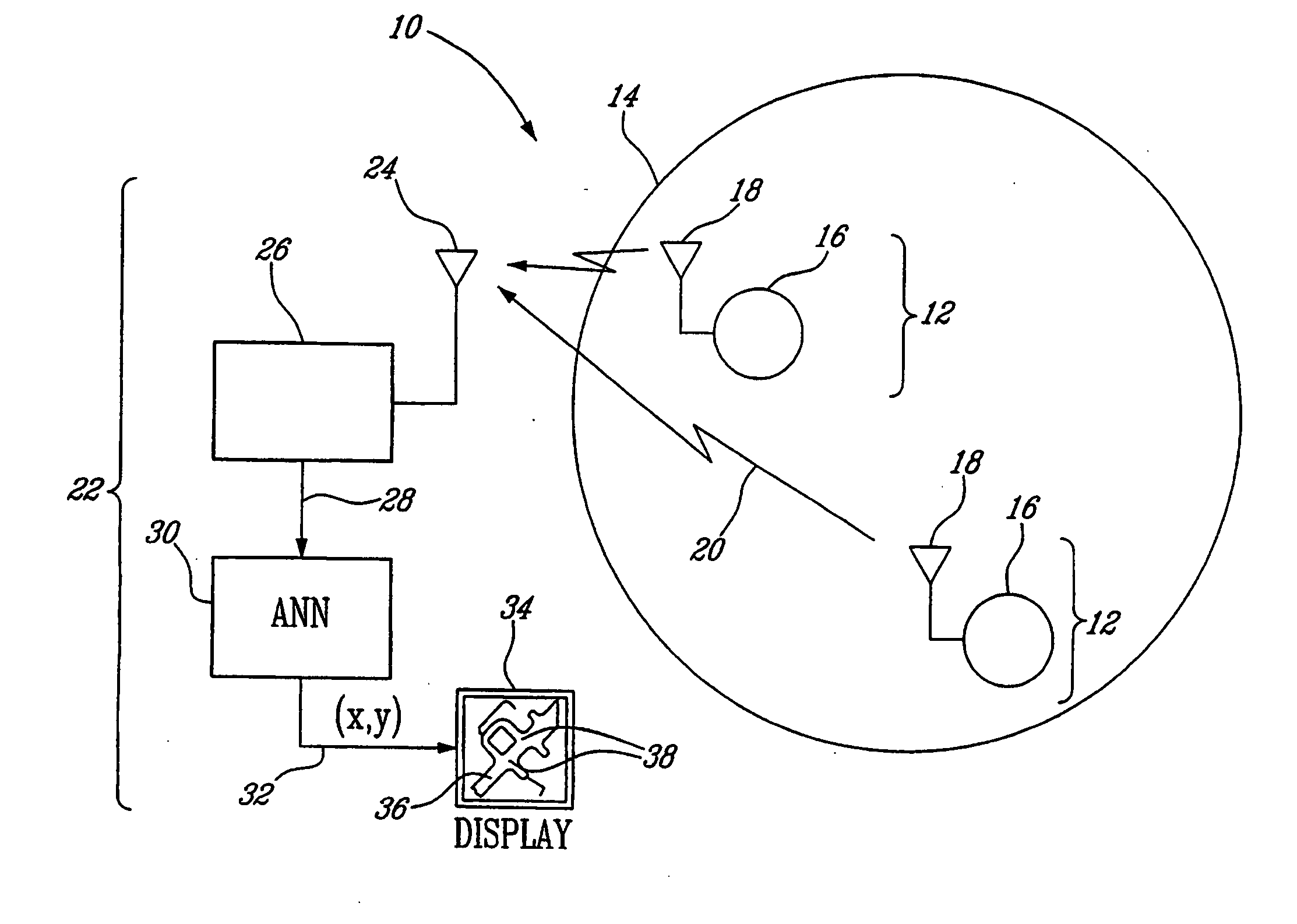
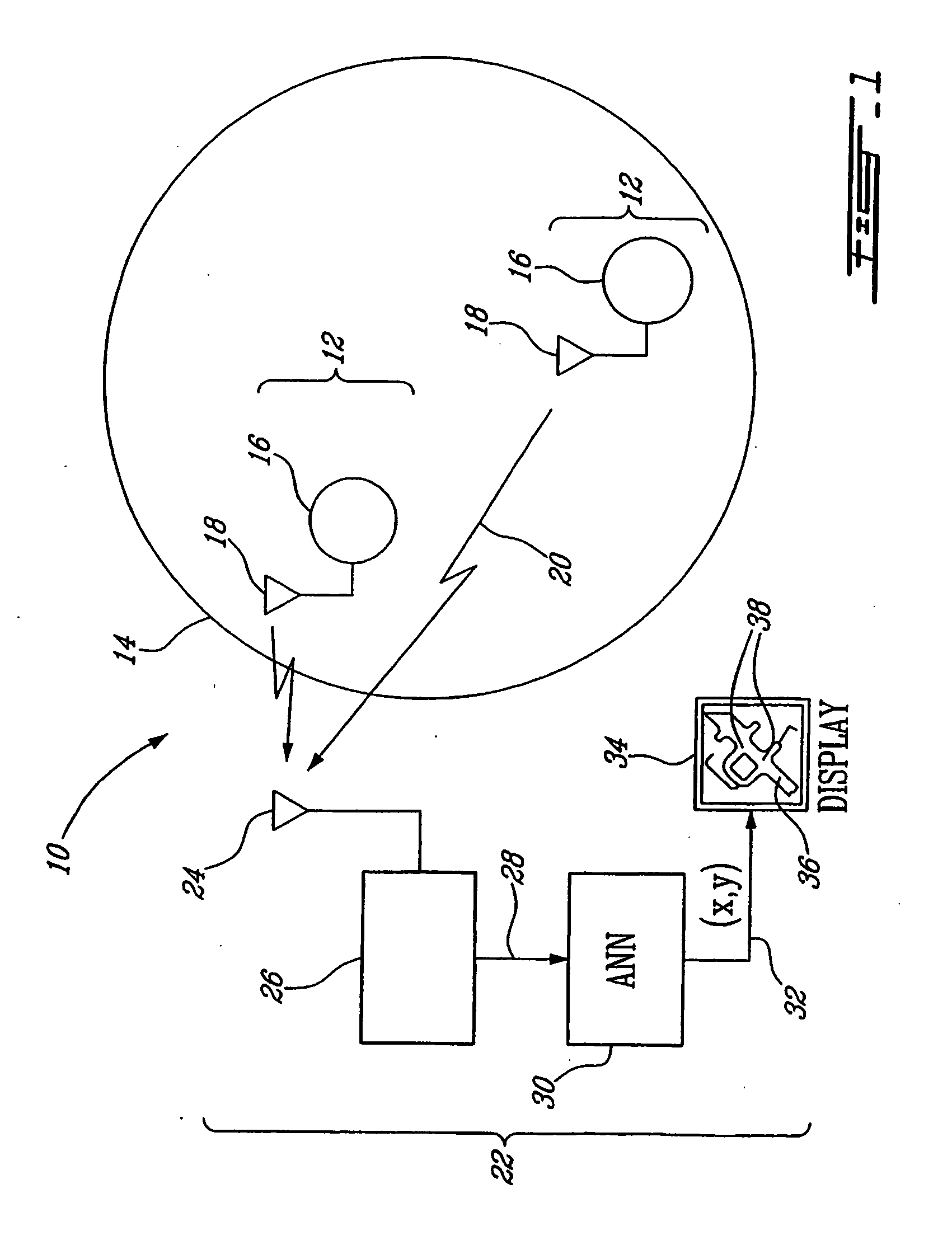
[0044] Referring now to FIG. 1, a geolocation system, generally referred to using the reference numeral 10, in accordance with an illustrative embodiment of the present invention will now be described. The geolocation system 10 consists of at least one mobile transmitter as in 12 located in a zone of interest 14. The zone of interest 14 is illustratively an underground gallery of a mineshaft comprised of a series of interconnected tunnels (not shown) and within which the mobile transmitters 12 are free to move, although other environments, such as hospitals, shopping malls, campuses and the like, could also provide suitable zones of interest.

[0045] The mobile transmitters 12 broadcast channel sounding signals generated by a radio frequency (RF) synthesizer 16 which are transmitted via an antenna 18 and a wireless RF channel 20 to a fixed receiver 22. The fixed receiver 22 comprises an antenna 24, a network analyser 26 for deriving the complex impulse response of the channel 20 from...


PUM


Abstract

A system and method for predicting the location of a transmitter in an indoor zone of interest, including fixed receiver for receiving a signal from the transmitter, the receiver deriving a fingerprint from the received signal, and a trained neural network. The trained neural network predicts the transmitter location from the fingerprint. The method includes receiving a signal transmitted from the transmitter at a fixed-location receiver, deriving a fingerprint from the received signal, supplying the fingerprint to a trained neural network, and reading the predicted location from the neural network. The artificial neural network may further be trained and include a plurality of weights and biases is also shown. The method may include collecting a training data set of fingerprints and corresponding locations, inputting the training data set to the neural network, and adjusting the weights and biases by minimising a sum of squares error function.

Description

RELATED APPLICATIONS [0001] This application is a continuation under 35 U.S.C. 111(a) of PCT / CA2004 / 001745, filed Sep. 24, 2004 and published as WO 2005 / 032189 A1, filed Apr. 7, 2005, which claimed priority under 35 U.S.C. 119(e) to U.S. Provisional Patent Application No. 60 / 505,753, filed Sep. 26, 2003, which applications and publication are incorporated herein by reference and made a part hereof.FIELD OF THE INVENTION [0002] The present invention relates to a method and system for indoor geolocation using an impulse response fingerprinting technique. In particular, the present invention relates to a method and system for locating a mobile station using a fingerprinting technique based on wideband channel measurements results in conjunction with a neural network as well as a method for training the neural network. BACKGROUND OF THE INVENTION [0003] One problem of growing importance in indoor environments is the location of people, mobile terminals and equipment. Indoor radio channe...

Claims


Application Information

Patent Timeline
IPC IPC(8): G06F19/00G06N3/08H04Q7/36
CPCG01S5/0252G01C21/206G01S5/0273G01S5/02525
Inventor NERGUIZIAN, CHAHEDESPINS, CHARLESAFFES, SOFIENE
Owner INSTITUT NATIONAL DE LA RECHERCHE SCIENTIFIQUE
Why Eureka
Try Eureka