
Reusable upper stage

a technology of upper stage and reusable upper stage, which is applied in the field of aerospace vehicles and spacecraft, can solve the problems of high cost of launch vehicle systems, inability to fully re-use earth-to-orbit launch vehicles, and inability to fly fully reusable earth-to-orbit launch vehicles, etc., and achieve the effect of re-use and minimal tim

Inactive Publication Date: 2007-01-18
BUEHLER DAVID
View PDF26 Cites 44 Cited by
  • Summary
  • Abstract
  • Description
  • Claims
  • Application Information

AI Technical Summary

Benefits of technology

[0021] The vehicle is designed to reenter nose-first in a ballistic manner. The aeroshell is covered by a transpiration or ablative thermal protection system for the reentry. The vehicle has an internal actuation system that allows the center of gravity of the stage to be varied during the reentry process thus allowing for the transition from a nose-first reentry to a side first semi-ballistic phase (which allows for greater cross-range movement than a purely ballistic reentry), and finally to a tail-first attitude for landing. The vehicle can be kept fairly stable throughout the entire reentry process.
[0025] In one embodiment, the spacecraft has fins to control its roll which allows the spacecraft to maneuver backward and forward in order to gain more cross range capability. Cross range capability is useful because it can allow the spacecraft to re-enter from various orbits which may not cross precisely over the landing site.
[0027] Just prior to landing the main engines are ignited to reduce the vehicle's velocity from terminal velocity to a safe landing speed prior to touchdown. Thrusters may also be used to maneuver to a precise landing point.
[0029] Propulsion modules built for the upper stage are made to operate optimally in vacuum. The atmospheric pressures on a propulsion module make the thrust direction unstable under normal atmospheric conditions with a standard nozzle. The nozzle must switch from a nozzle designed for a vacuum environment to one for operation near the Earth's surface in dense atmosphere. Various methods can be employed to accomplish this. In one embodiment, a circular gas injector is attached to the propulsion nozzle to force an even separation of the gas from the nozzle wall at a point where the jet pressure is nearly equal to sea-level ambient pressure. In another embodiment, a dual bell nozzle is used, which contains an inflection point that forces even separation at near sea-level ambient pressures. Both of these embodiments prevent the flow from reattaching to the chamber wall and thus producing large unwanted side-loads on the nozzle. In another embodiment, the lower section of the nozzle is jettisoned to reduce the expansion ration of the nozzle.
[0032] This system of the current invention has many advantages over other proposed and existing reusable systems. The semi-ballistic trajectory allows for a degree of cross-range maneuvering during reentry. Using the propulsion module in a powered vertical landing provides much higher landing precision than is typical. This concept also delivers significant operational savings by not requiring the recovery of a stage from the sea or needing to search for a stage after it has landed. Also, by avoiding corrosive sea water, it will be easier to prepare the vehicle for its next flight in a rapid manner. Most importantly, the system is simple and much less expensive than other options. It involves a minor amount of additional hardware over that found on a typical upper stage.

Problems solved by technology

This stems from the generally high cost of launch vehicle systems.
Most current expendable launch vehicles cost tens of millions of dollars to build only to be tossed away after each launch.
However, in spite of the desirability of being able to fully reuse the launch vehicle, and in spite of the many concepts that have been proposed, to this date no fully reusable Earth-to-orbit launch vehicle has flown.
In fact, there is only one currently operating example of a reusable launch vehicle, the Space Shuttle, and it in fact is only partially reusable requiring extensive refurbishment, check-out, and inspection between each launch.
Of the various proposed solutions, almost all of them suffer from various drawbacks and disadvantages.
The drawbacks to these options is that they generally are very volume inefficient, the wings are often massive, and there are often severe strains put on the thermal protection systems of the vehicles.
While this may work fine for a suborbital vehicle, these problems can become quite severe for an orbital vehicle.
When the complicated aerodynamic steering and landing equipment such as flaps and landing gear is added, the result is a fairly expensive and complicated system.
Putting a body that can generate aerodynamic lift at the end of a long rocket causes significant steering issues for the rocket.
If it is horizontally launched, it either requires a very large flying carrier vehicle, or it requires very heavy wings and landing gear to be able to handle that much weight on takeoff.
These also have problems.
One is that parachute recovery usually requires the craft to be recovered at sea which has usually been done in the past with an aircraft carrier, which are very expensive to operate.
There can also be problems with actually reusing the vehicle due to seawater corrosion.
Some capsules like those used by Russia and China are recovered on land, but this requires braking rockets and such vehicles are relatively limited as to where they may land.
One difficulty with a parachute descent is that it offers very little precision in the system's landing location.
Parachutes also have very limited cross-range capability.
There is also the risk that the retrorockets might not fire correctly or that there might be substantial impact damage if using airbags for final landing.
However, these suffer from the fact that their entire weight must be put into orbit and brought back down again.
This greatly reduces there potential payload and makes them much less economically feasible even if they prove to be technically possible.
For most TSTO designs, the upper stage is usually the more expensive and complicated in spite of being physically much smaller than the lower stage.
However, while the prospect of reusing the upper stage is attractive financially, it is also complex to develop and test.

Method used


Image

  • Reusable upper stage
  • Reusable upper stage
  • Reusable upper stage

Examples


Embodiment Construction

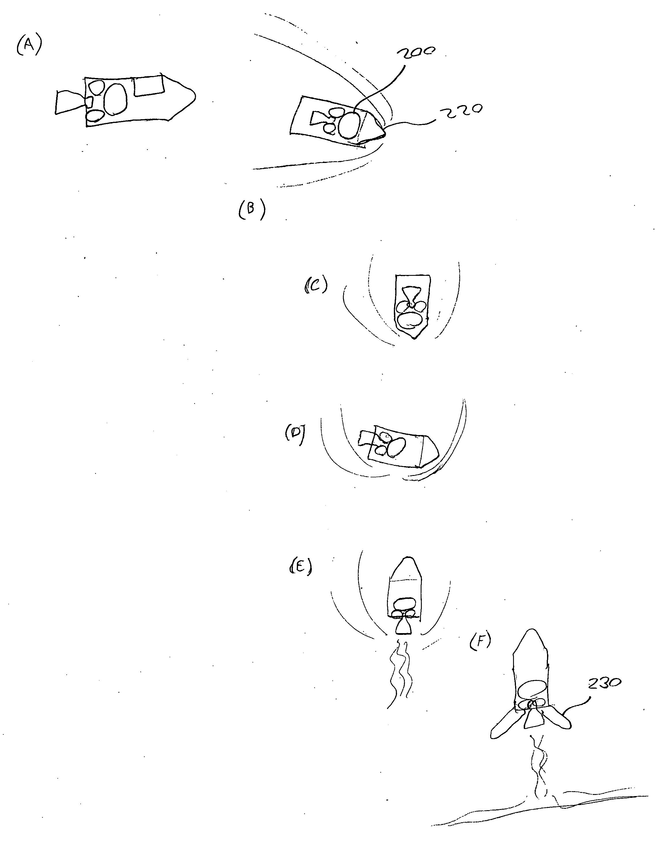
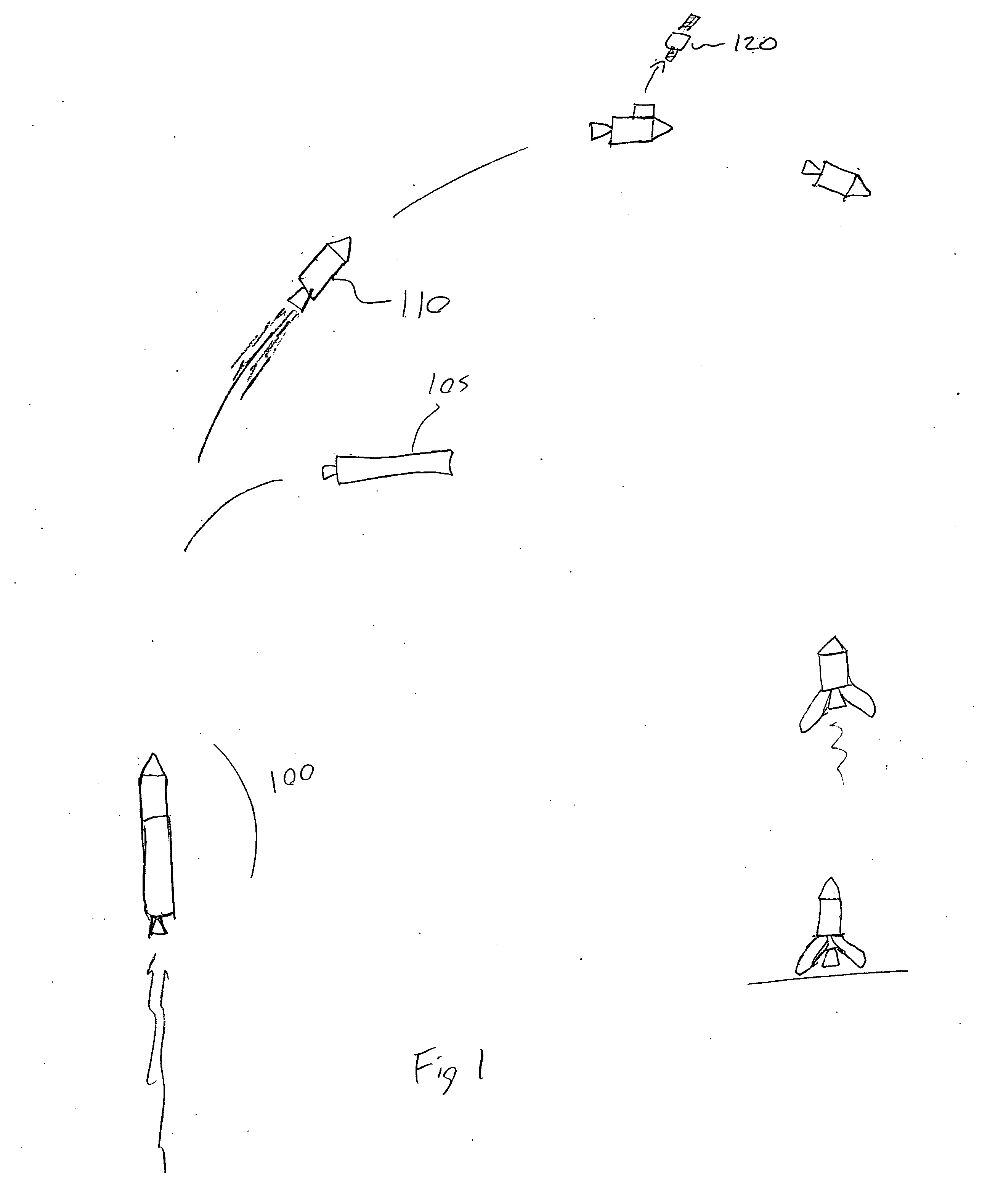
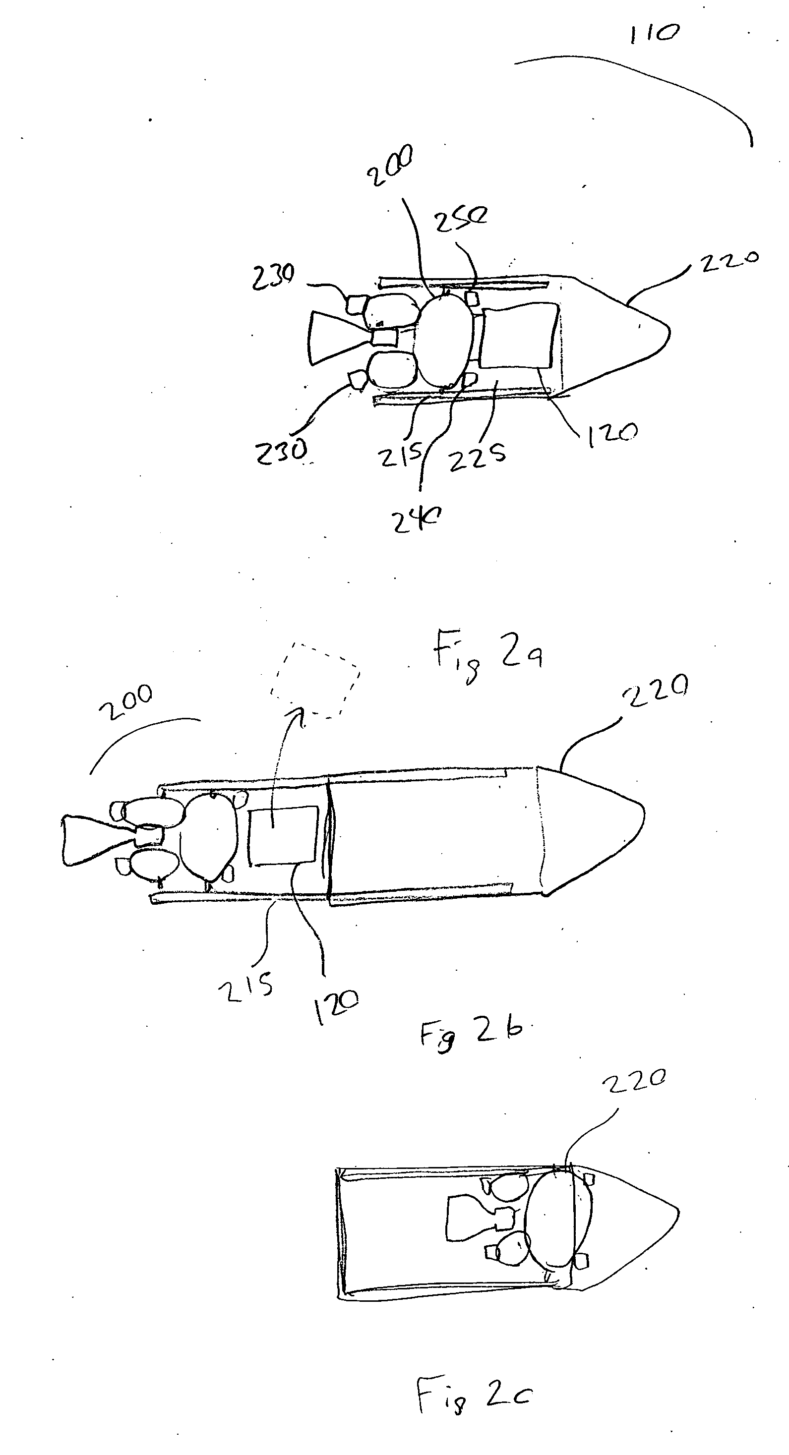
[0055]FIG. 1 is a pictorial illustration of a payload launch sequence of the two stage rocket. As depicted, the two stage rocket (100) includes: one or more lower stages (105) releasably connected to an upper stage (110), and a payload (120) that is carried on board the upper stage.

[0056] Typically two or more stages are used to send a rocket with payload into space. The rocket shown in this figure uses only two stages, however the unique aspects of this patent can also be applied to a rocket of three or more stages.

[0057] In one embodiment, the reusable upper-stage further comprises at least one releasably connected conduit configured allow the stage to be launched with partially filled propellant tanks to allow the main engine to be used to lift the stage away from the lower stage in the event of a malfunction, yet still provide enough acceleration due to the reduced mass of the stage, then allow propellant stored on the lower stage to be transferred to the upper stage prior to ...


PUM


Abstract

This patent describes a reusable upper-stage, that utilizes a position-adjustable propulsion module and payload compartment, an aeroshell, a guidance and control system, and a deployable landing apparatus. The position-adjustable upper-stage propulsion module is shifted forward in the aeroshell prior to reentry into the atmosphere to allow the stage to reenter in a stable, nose-first orientation. It is shifted back to allow the stage to fall tail first and use its engine to do a final deceleration and a powered soft landing, supported by deployable landing apparatus.

Description

[0001] This application claims the benefit of provisional application 60 / 600,568 filed Aug. 11, 2004 entitled “Reusable Upper Stage”. [0002] It also references USPTO disclosure document number 548532 filed Mar. 9, 2004, entitled “Reusable Upper Stage”.BACKGROUND OF THE INVENTION [0003] 1. Field of the Invention [0004] The present invention is related to aerospace vehicles and transport systems and, more particularly, to Earth-to-orbit aerospace vehicles used for the deployment of payloads, such as satellites, into low Earth orbits. [0005] 2. Description of Related Art [0006] It is widely held in the Earth-to-orbit launch community that one of the single biggest keys to reducing the currently high costs of launching anything into orbit is by making the launch vehicle hardware fully reusable. This stems from the generally high cost of launch vehicle systems. Most current expendable launch vehicles cost tens of millions of dollars to build only to be tossed away after each launch. If t...

Claims


Application Information

Patent Timeline
IPC IPC(8): B64G1/00
CPCB64G1/14
Inventor BUEHLER, DAVID
Owner BUEHLER DAVID
Learn More