Spindle motor

a spindle motor and spindle technology, applied in the direction of dynamo-electric machines, magnetic circuit shape/form/construction, structural associations, etc., can solve the problems of reducing the life of the motor, reducing reducing the overall anti-vibration property. , to achieve the effect of increasing the number of turns of the coil, high torque, and small variance in the magnetism center of the motor

Active Publication Date: 2007-01-18
PHC HLDG CORP
View PDF5 Cites 40 Cited by
  • Summary
  • Abstract
  • Description
  • Claims
  • Application Information

AI Technical Summary

Benefits of technology

[0023] According to the present invention, since bent core sheets (thin magnetic plates) are laminated to form a stator core, salient pole teeth portions of the stator core faces a surface of the rotor magnet substantially perpendicularly while keeping winding space sufficiently. Thus, magnetic force lines of the rotor magnet pass through the stator core at right angles and the magnetic force of the rotor magnet effectively influence rotational power. In bent portions, a thickness of the core sheet is made thinner than that of other portions. Thus, when the stator core is formed by laminating the core sheets, the tip portions of the salient pole teeth portions do not spread out and no gap is generated between the core sheets.
[0025] According to the present invention, the stator core is formed by laminating core sheets bent at first bent portions and second bent portions. Since the core sheets are bent at the first bent portions, the salient pole teeth portions faces a surface of a rotor magnet substantially perpendicularly. Thus, magnetic force lines of the rotor magnet pass through the stator core at right angles and the magnetic force of the rotor magnet effectively influence rotational power. Further, since the core sheets are bent at the second bent portions, the salient pole arm portions can be set at a desirable position to maximize the number of turns of the coil. In the first and second bent portions, a thickness of the core sheet is made thinner than that of other portions. Thus, when the stator core is formed by laminating the core sheets, the tip portions of the yoke portions and the salient pole teeth portions do not spread out and no gap is generated in yoke portions and the salient pole teeth portions between the core sheets.
[0026] According to the present invention, a stator core is bent in bent portions between salient pole arm portion around which windings are wound and salient pole teeth portions facing a rotor magnet. With such a structure, the salient pole arm portions can be disposed at an approximately halfway between the base and the hub. In this way, a spindle motor having an increased number of turns of the windings wound around the salient pole arm portions and a high torque can be achieved.
[0027] In the bent portions, the stator core is bent such that the salient pole teeth portions and the salient pole arm portions are parallel to each other. Thus, the salient pole teeth portions face a surface of the magnet substantially perpendicularly. Thus, magnetic force lines of the rotor magnet pass through the stator core at right angles and the magnetic force of the rotor magnet effectively influence rotational power.
[0028] Further, since a thickness of the stator core sheet forming the stator core in the bent portions is made thinner than that of other portions, no gap is generated in the salient pole teeth portions between the stator core sheets adjacent to each other when the stator core sheets pressed and bent with one mold are laminated. The magnetism property does not deteriorate, and no vibration and noise is generated.
[0029] Moreover, the position of the magnetism center of the stator core becomes easy to be set. A variance in the magnetism centers among the motors also becomes small. This enables an accurate adjustment of attractive forces.

Problems solved by technology

In recent years, electronic equipment is becoming smaller and smaller.
An anti-vibration property as a whole device may also deteriorate.
When an amount of the oil is decreased in the later stage of the life of the bearing, the life may be shortened due to a bearing contact.
In addition, vibration and noise of a spindle motor are also affected by the shift length of the magnetic centers.
Further, a position of the magnetic center of the stator core is difficult to be determined.
Thus, there is large variance in attractive forces and motor properties such as an amount of floating and the life are not stabilized.
The second problem is due to a method for producing the stator.
Furthermore, leakage flux from the stator core 118 increases and the magnetic property deteriorates.
This increases power loss.
It is also difficult to predict where the magnetic center of the stator core is, and a variance in the magnetic centers among the motors becomes large.
Therefore, there is a large variance in attractive forces and the motor properties such as an amount of floating, the life, and the like are not stabilized.
If one mold is used for all the core sheets, a large strong bending working machine is required and a process cost is increased significantly.

Method used


Image

  • Spindle motor
  • Spindle motor
  • Spindle motor

Examples


embodiment 1

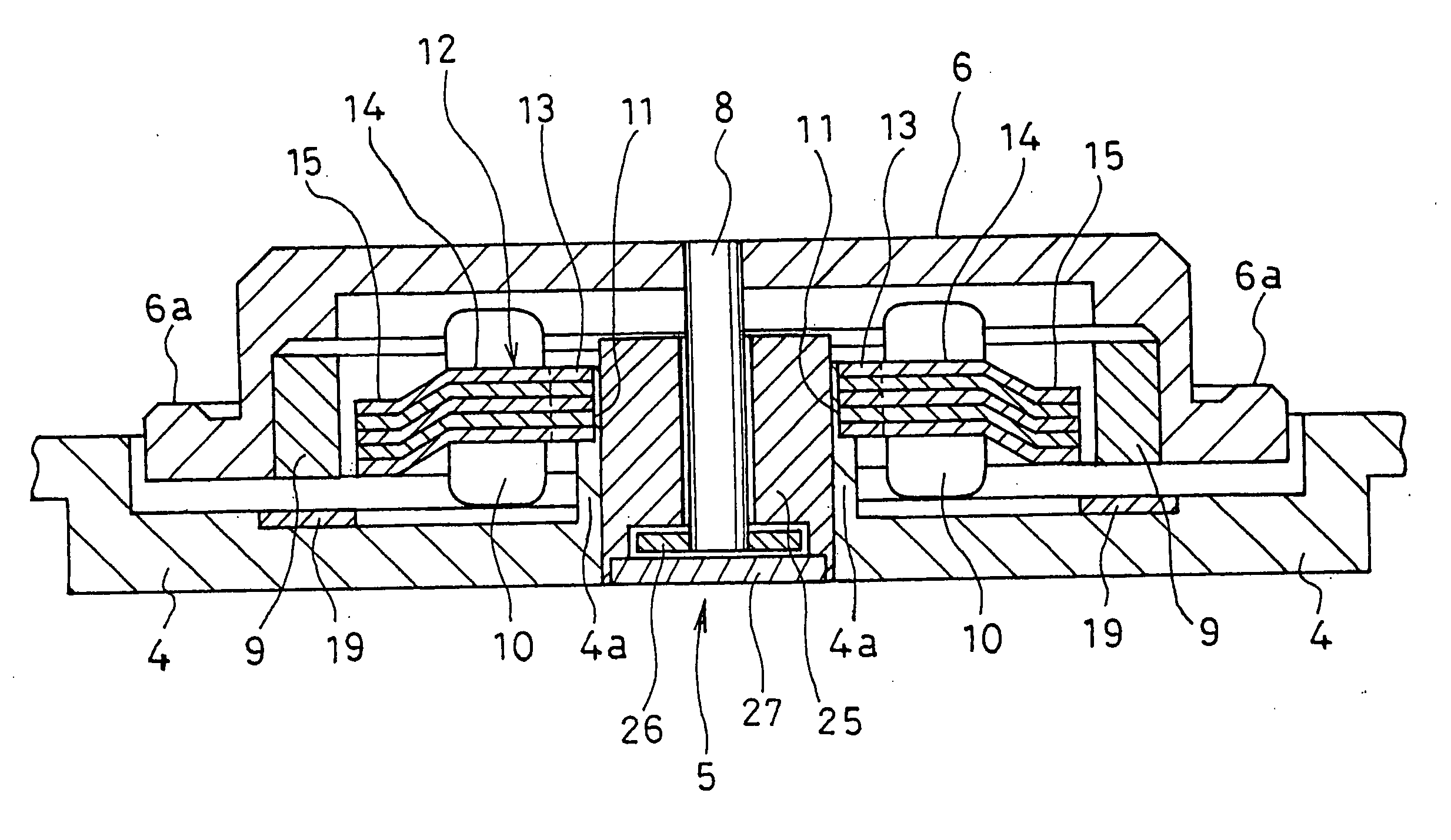
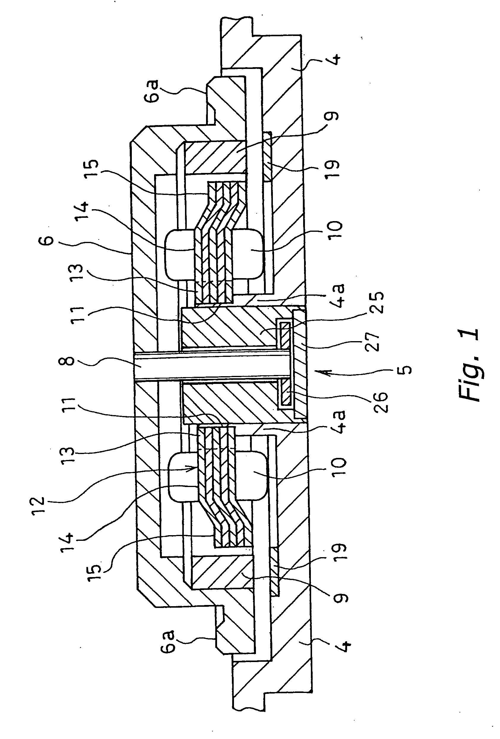
[0049]FIG. 1 is a cross-sectional view of a spindle motor of an external rotor type according to Embodiment 1 of the present invention. As shown in FIG. 1, a base 4 which is a fixed portion of the spindle motor has a bearing support 4a of a tubular shape in its central portion. A bearing unit 5 is fixed into a hole of the bearing support 4a. The bearing unit 5 is a hydrodynamic bearing device of an axis-rotation type and supports a shaft 8 so as to be rotatable. To the shaft 8, a hub 6 having a plate-like shape is attached.

[0050] There are two types of hydrodynamic bearing devices: an axis-rotation type and an axis-fixed type. Both types can be applied to Embodiment 1. A radial bearing and a thrust bearing of the hydrodynamic bearing devices may have structures as described below. In the radial bearing, a sleeve is fitted to an outer periphery of an axis with a predetermined gap interposed therebetween, and a lubrication fluid is filled in the gap between the axis and the sleeve. A...

embodiment 2

[0063] The spindle motor according to Embodiment 2 of the present invention will be described with reference to FIGS. 8 and 9. Embodiment 2 relates to a spindle motor of an internal motor type. FIG. 8 is a cross-sectional view of the spindle motor. In FIG. 8, a base 34 which is a fixed portion of the spindle motor has a bearing support 34a in its central portion and has a bearing unit 35 fixed to a hole of the bearing support 34a. The bearing unit 35 supports a shaft 38 so as to be rotatable. To the shaft 38, a hub 36 is attached. For example, a magnetic disc or an optical disc is attached to a disc receiving surface 36a of the hub 36. A rotor magnet 39 is attached to the hub 36.

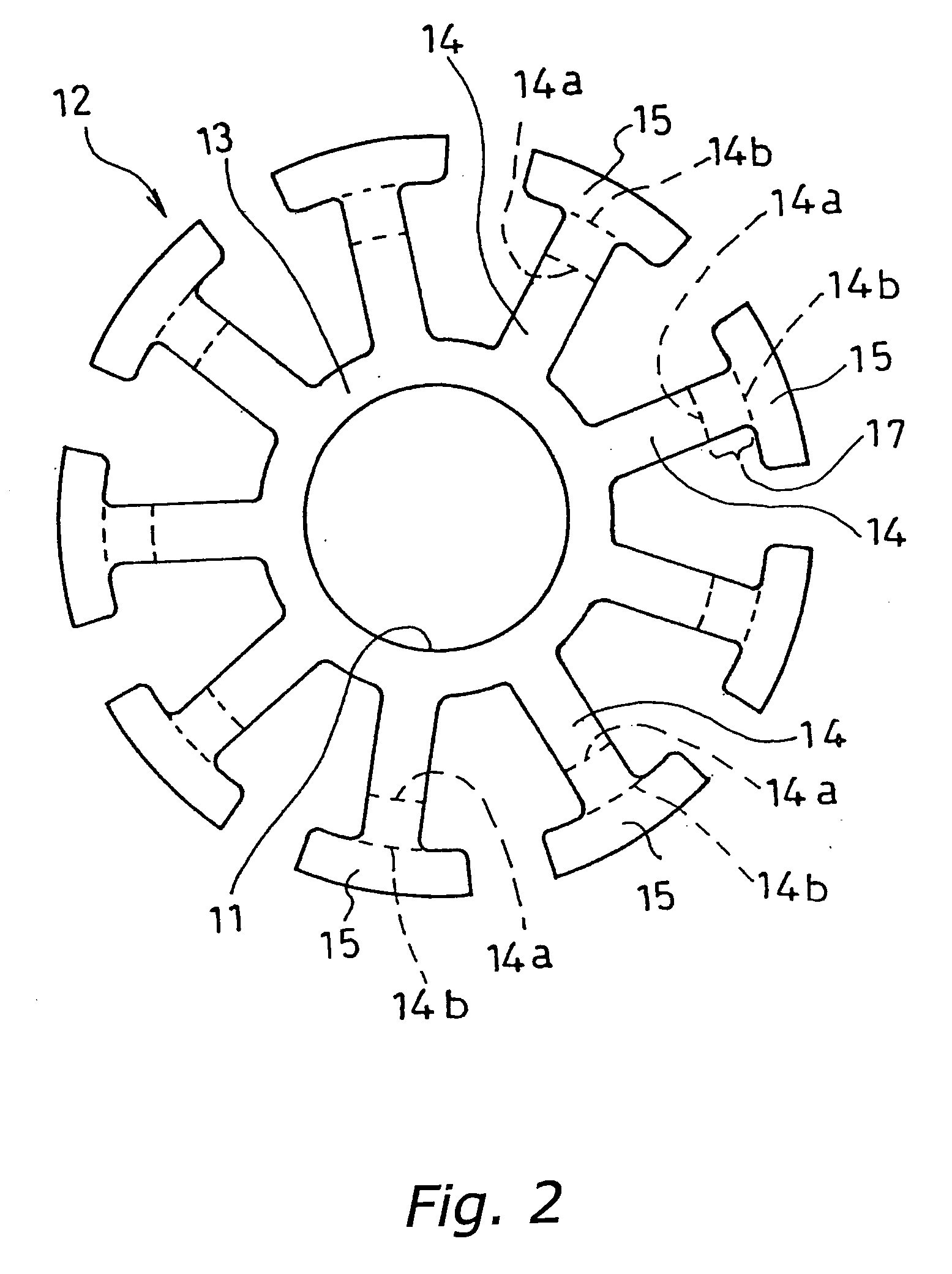
[0064] A stator core 40 is provided on a support 34b in an outer peripheral portion of the base 34. As shown in a plain view of FIG. 9A, the stator core 40 includes nine salient pole arm portions 42 protruding from a yoke portion 43 having a ring shape in an inward direction. The spindle motor is a motor wi...

embodiment 3

[0071] A spindle motor according to Embodiment 3 of the present invention will be described with reference to FIG. 10. Embodiment 3 relates to a spindle motor of an internal rotor type. The spindle motor has a stator core 60 which has a different structure from that of the stator core 40 of the spindle motor according to Embodiment 2 as shown in FIG. 8. However, other components are the same as those shown in FIG. 8. Therefore, elements same as those in FIG. 8 are denoted by the same reference numerals and overlapping explanation is omitted.

[0072] As shown in FIG. 10, the stator core 60 has a shape similar to that of the stator core 40 shown in FIG. 9A except for the shape around a yoke portion 63. A structure of the yoke portion 63 will be described below in detail.

[0073] The stator core 60 is fixed to the base 34 with a lower end surface of the yoke portion 63 being supported by a supporting portion 34b provided on the base 34. A first bent portion 66 is formed between the yoke ...


PUM


Abstract

In a spindle motor in which teeth portions of a stator core formed by laminating magnetic plates are bent in order to increase the number of turns of the stator windings, a gap in the teeth portions between the magnetic plates is avoided and a precise attractive force adjustment becomes possible. The stator core is bent such that its teeth portions faces a surface of a rotor magnet at right angles, and the teeth portions and salient pole arm portions around which windings are wound are substantially parallel to each other. The salient pole arm portions locate approximately halfway between a lower surface of a hub and an upper surface of a base. Further, a thickness of a magnetic plate is set to be 0.5 to 0.9 times that of other portions.

Description

BACKGROUND OF THE INVENTION [0001] 1. Field of the Invention [0002] The present invention relates to a spindle motor for rotating magnetic discs, optical discs and the like, and a brushless motor having a structure similar to that of the spindle motor. [0003] 2. Description of the Related Art [0004] In recent years, electronic equipment is becoming smaller and smaller. Thus, there is a growing demand for hard disc drives (HDDs) incorporated therein to become smaller and thinner. For example, until few years ago, HDDs for discs having a diameter of 3.5 inches or 2.5 inches had been used commonly. However, recently, HDDs for discs having a diameter of 1.8 inches or smaller, that is, 1 inch or 0.85 inches are becoming popular. When the disc diameter is reduced, motors such as spindle motors, brushless motors and the like for rotating the disc also have to become smaller and thinner. A reduction in size and thickness of motors is required not only in the field of HDDs but also in many o...

Claims


Application Information

Patent Timeline
Patent Type & Authority Applications(United States)
IPC IPC(8): H02K7/00H02K21/12
CPCH02K1/146H02K21/24H02K21/16
Inventor WAKITANI, AKIHIKOJYONO, MASAHIROYOSHITSUGU, TAKAOASHIZAKI, YOSHIHIRO
Owner PHC HLDG CORP
Why Eureka
Try Eureka