Method for assisting video compression in a computer system

a computer system and video data technology, applied in the field of video data compression, can solve the problems of loss of image clarity, video data streams typically have extremely large bandwidth requirements, computer systems often cannot keep up with the computational requirements of video data, etc., and achieve the effect of improving the handling of video data and facilitating video data compression

Inactive Publication Date: 2007-01-18
ROUND ROCK RES LLC
View PDF25 Cites 3 Cited by
  • Summary
  • Abstract
  • Description
  • Claims
  • Application Information

AI Technical Summary

Benefits of technology

[0008] One embodiment of the present invention provides a method that facilitates compression of video data in a computer system by performing the time-consuming task of computing the difference between successive frames of video data independently from the central processing unit. This frees the often-overburdened central processing unit from performing this time-consuming compression operation and can thereby improve the handling of video data. Thus, one embodiment of the present invention can be characterized as a method for compressing video data in a computer system. This method includes receiving a stream of data from a current video frame in the computer system. It also includes computing a difference frame from the current video frame and a previous video frame “on-the-fly” as the current video frame streams into the computer system. The method additionally includes storing the difference frame in a memory in the computer system.

Problems solved by technology

As video data is increasingly used in computer systems in applications such as video conferencing and video recording, computer systems often cannot keep pace with the computational requirements of video data.
Video data streams typically have extremely large bandwidth requirements that can tax the capabilities of even the most high-speed processor to compress the video data for storage, or for transmission across a computer network or a telephone system.
This compression is typically performed by a central processing unit (CPU) in a computer system with a resulting loss in image clarity due to the failure of the CPU to keep pace with the video data.
Complex scenes, having many elements that are in motion represent the greatest challenge because they place a tremendous burden on the CPU during the compression and data transfer processes.
A time-consuming step in the compression of video data is to compute differences between successive video frames.

Method used


Image

  • Method for assisting video compression in a computer system
  • Method for assisting video compression in a computer system
  • Method for assisting video compression in a computer system

Examples


first embodiment

Description of the Computer System

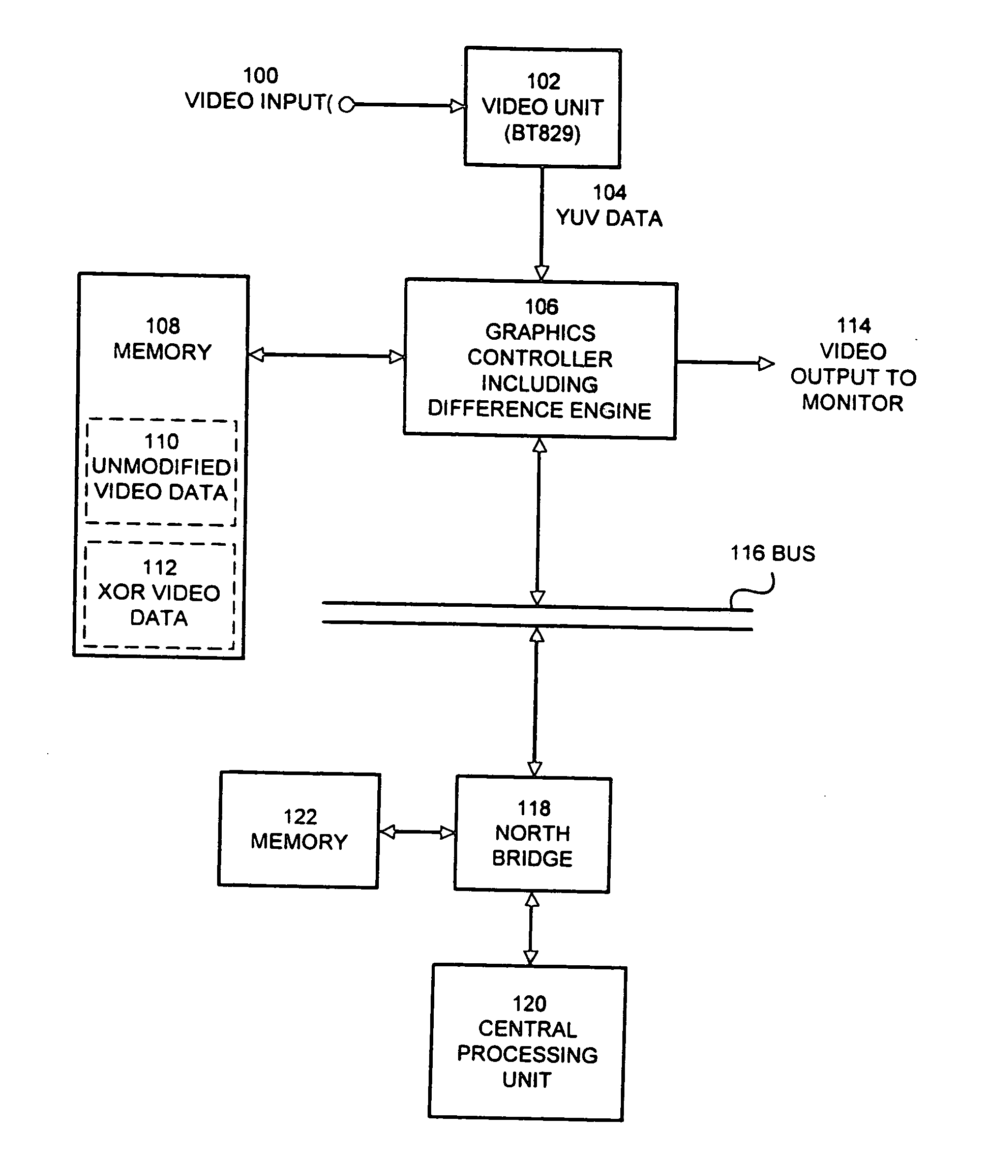
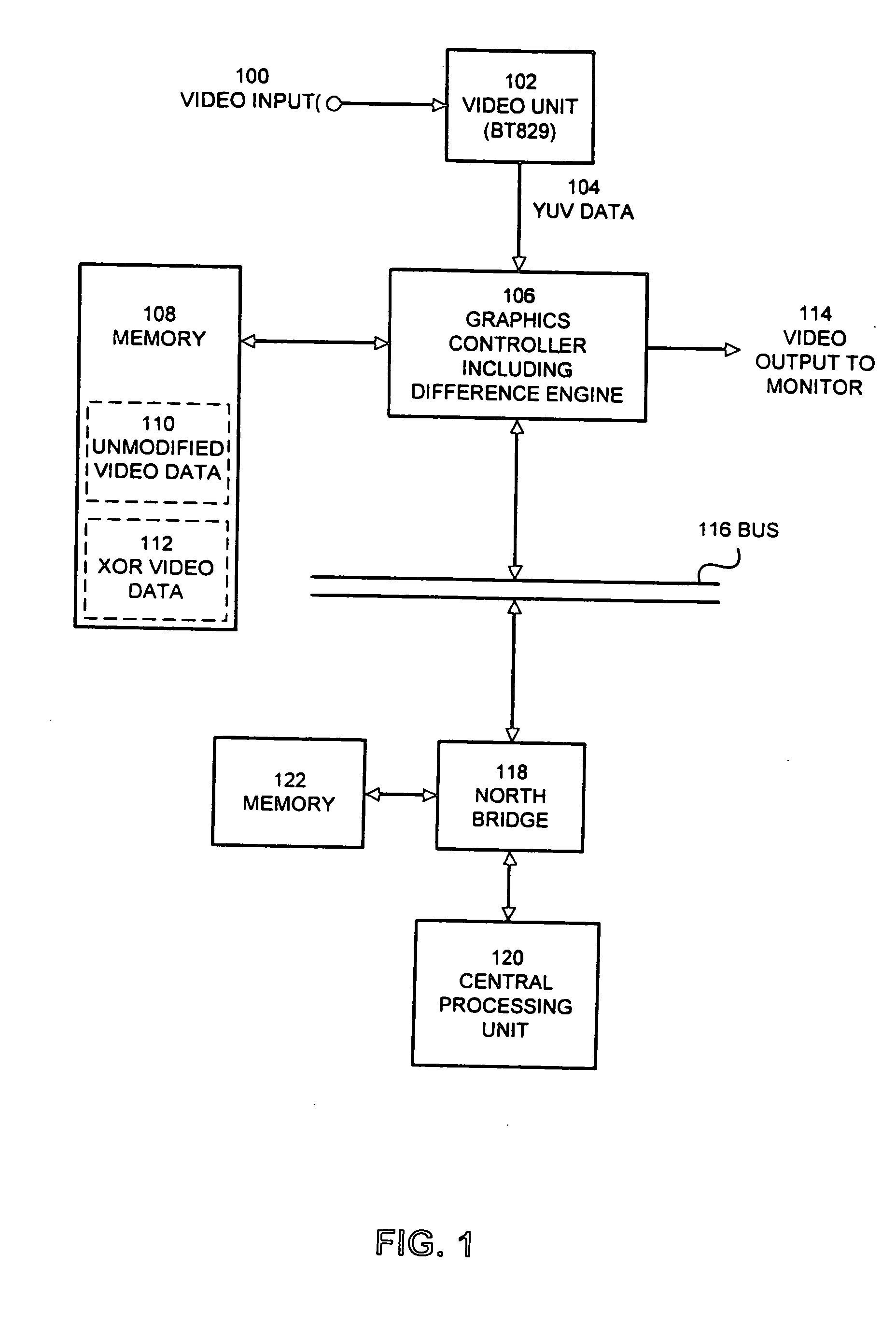
[0024]FIG. 1 illustrates a computer system including a graphics controller with a difference engine 106 in accordance with an embodiment of the present invention. The embodiment illustrated in FIG. 1 includes central processing unit (CPU) 120, which is coupled through north bridge 118 to memory 122 and bus 116. CPU 120 may be any type of central processing unit that can be used in a computer system. This includes, but is not limited to, a microprocessor CPU, a mainframe CPU and a device controller CPU. North bridge 118 forms part of the “core logic” for the computer system. This core logic ties together and coordinates operations of components in the computer system. Memory 122 can be any type of semiconductor memory that can be used in a computer system. Bus 116 can be any type of computer system bus. In one embodiment, bus 116 includes a PCI bus.

[0025] Bus 116 is also coupled to graphics controller 106, which includes a difference engine. In this...

second embodiment

Description of a Second Embodiment

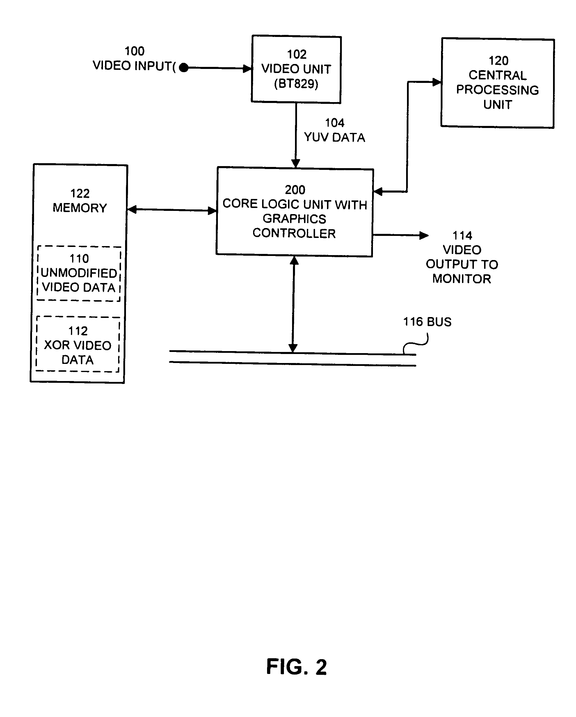
[0029]FIG. 2 illustrates a computer system including a graphics controller incorporated into a core logic unit 200 in accordance with another embodiment of the present invention. This embodiment is similar to the embodiment illustrated in FIG. 1, except that graphics controller 106 and north bridge 118 from FIG. 1 are combined into a single core logic unit with graphics controller 200. Additionally, memory 108 and memory 122 from FIG. 1 are combined into a single memory 122 in FIG. 2.

[0030] In the embodiment illustrated in FIG. 2, core logic unit 200 includes circuitry to compute the difference between successive video frames as well as circuitry to perform other graphics controller functions.

[0031] The embodiment illustrated in FIG. 2 operates in the same way as the embodiment illustrated in FIG. 1, except that in FIG. 2, unmodified video data 110 and XOR video data 112 are not stored in a separate graphics memory 108, but are rather stored in th...


PUM


Abstract

One embodiment of the present invention provides a method that facilitates compression of video data in a computer system by performing the time-consuming task of computing the difference between successive frames of video data independently from the central processing unit. This frees the often-overburdened central processing unit from performing this time-consuming compression operation and can thereby improve the handling of video data. Thus, one embodiment of the present invention can be characterized as a method thr compressing video data in a computer system. This method includes receiving a stream of data from a current video frame in the computer system. It also includes computing a difference frame from the current video frame and a previous video frame “on-the-fly as the current video frame streams into the computer system. The method additionally includes storing the difference frame in a memory in the computer system.

Description

CROSS-REFERENCE TO RELATED APPLICATIONS [0001] This application is a continuation of application Ser. No. 09 / 048,933, filed Mar. 26, 1998, pending. The subject matter of that application is related to the subject matter in a co-pending non-provisional application by the same inventor entitled, “Apparatus for Assisting Video Compression in a Computer System,” having Ser. No. 09 / 048,932, and filing date Mar. 26, 1998, now U.S. Pat. No. 6,987,545, issued Jan. 17, 2006.BACKGROUND OF THE INVENTION [0002] 1. Field of the Invention [0003] The present invention relates compressing video data, and more specifically to a method that provides assistance to a computer system in compressing a stream of video data on-the-fly, as the video data streams into the computer system. [0004] 2. Related Art [0005] As video data is increasingly used in computer systems in applications such as video conferencing and video recording, computer systems often cannot keep pace with the computational requirements...

Claims


Application Information

Patent Timeline
Patent Type & Authority Applications(United States)
IPC IPC(8): H04N11/02H04N7/36
CPCH04N19/503H04N21/4143
Inventor KLEIN, DEAN A.
Owner ROUND ROCK RES LLC
Why Eureka
Try Eureka