Remotely controlled antenna and method

a remote control and antenna technology, applied in the field of remote control television antennas, can solve the problems of poor radio performance of rod antennas, disadvantaged broadcast television services, and inability to achieve unity or less gain

Active Publication Date: 2007-01-18
GENERAL WIRELESS OPERATIONS +1
View PDF18 Cites 15 Cited by
  • Summary
  • Abstract
  • Description
  • Claims
  • Application Information

AI Technical Summary

Benefits of technology

[0016] The present invention also teaches an antenna system for receiving radio waves and for operation in conjunction with a remote controller that transmits encoded radio signals with control data that may include gain state data, antenna position data, location data, and a store command. The antenna systems includes an antenna designed to receive the radio waves in a band of frequencies from 470 megahertz to 890 megahertz and that outputs a radio frequency signal. The antenna includes a three-element log periodic array disposed upon a printed circuit board substrate that is resonant in an operating band of frequenci

Problems solved by technology

However, broadcast television service is disadvantaged by the vagaries of radio wave propagation.
Each antenna design includes compromises between size, cost, radio performance, ease of installation, and operating convenience.
However, the radio performance of the rod antenna is poor having a gain that may be unity or less.
Users of rod antennas frequently struggle to get decent picture and sound quality, especially at lower frequency channels where a large physical structure is needed for the antenna to be resonant and couple radio energy efficiently.
Rod antennas are only effective in very strong signal strength environments, at close ranges to television broadcast transmitters.
These antennas can be very large, requiring outdoor mounts, rooftop mounts, and long feed lines.
They are expensive and difficult to install.
Stil

Method used


Image

  • Remotely controlled antenna and method
  • Remotely controlled antenna and method
  • Remotely controlled antenna and method

Examples


Embodiment Construction

[0050] Illustrative embodiments and exemplary applications will now be described with reference to the accompanying drawings to disclose the advantageous teachings of the present invention.

[0051] While the present invention is described herein with reference to illustrative embodiments for particular applications, it should be understood that the invention is not limited thereto. Those having ordinary skill in the art and access to the teachings provided herein will recognize additional modifications, applications, and embodiments within the scope hereof and additional fields in which the present invention would be of significant utility.

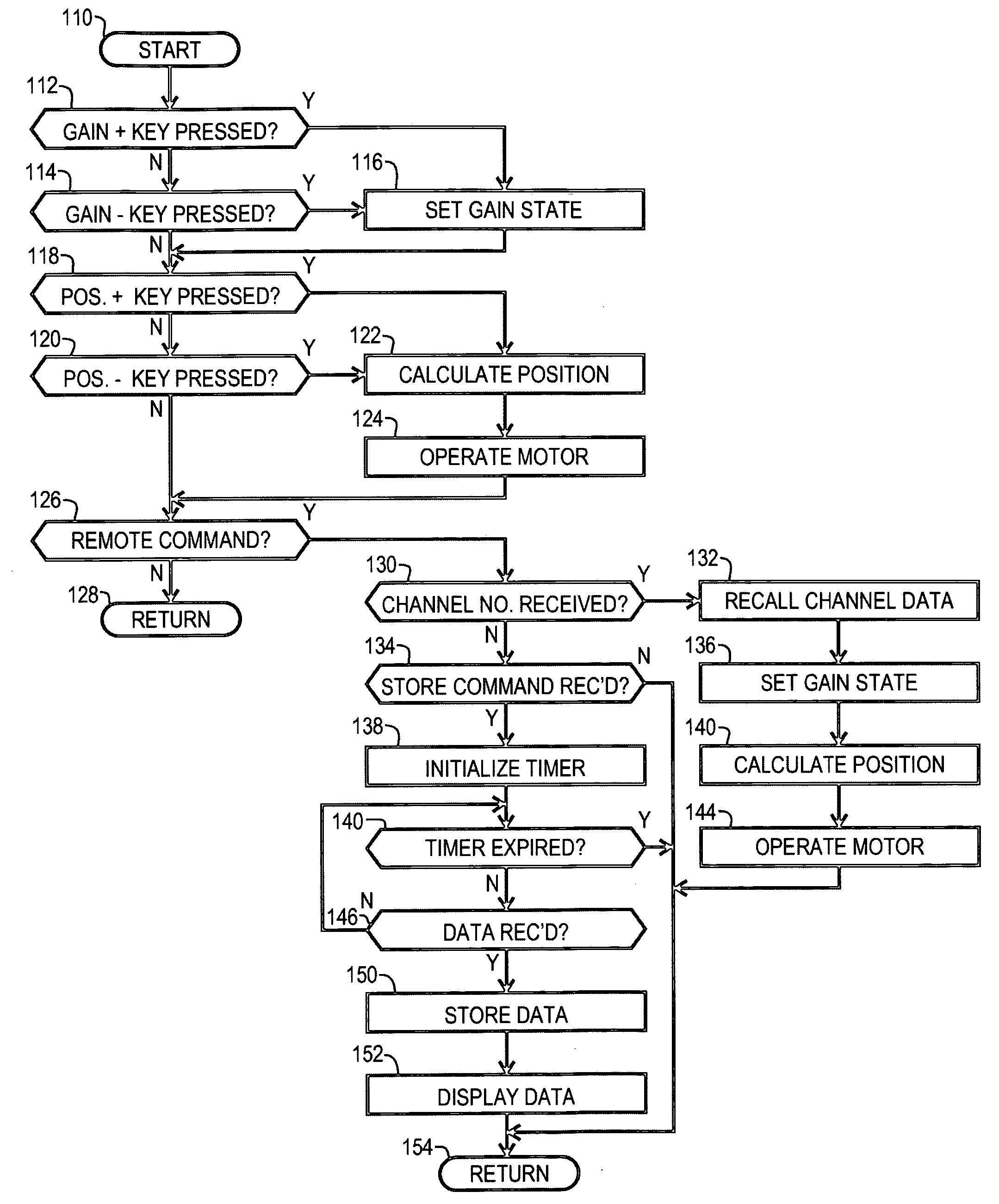
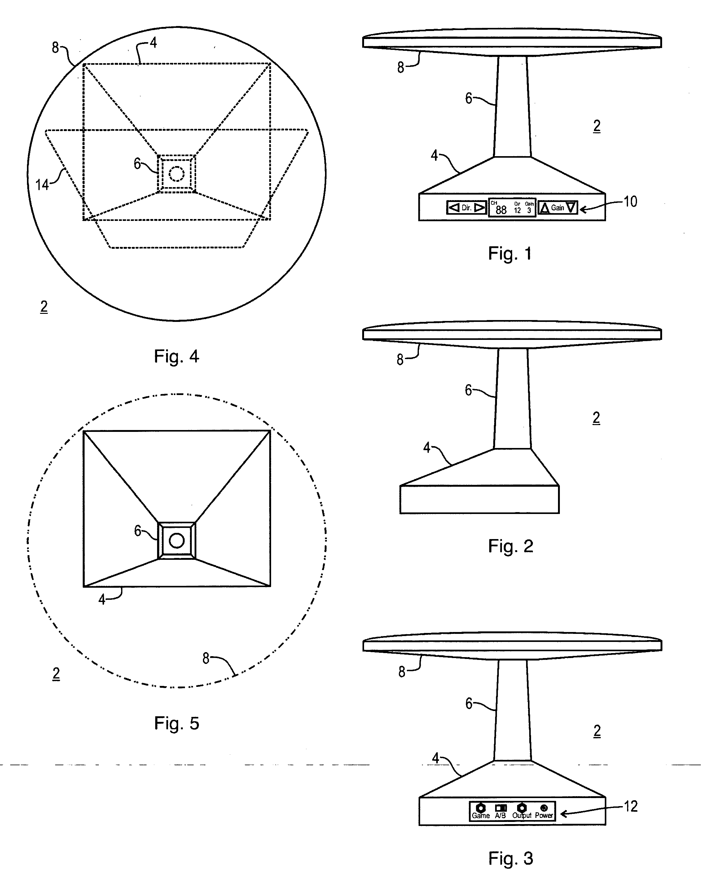
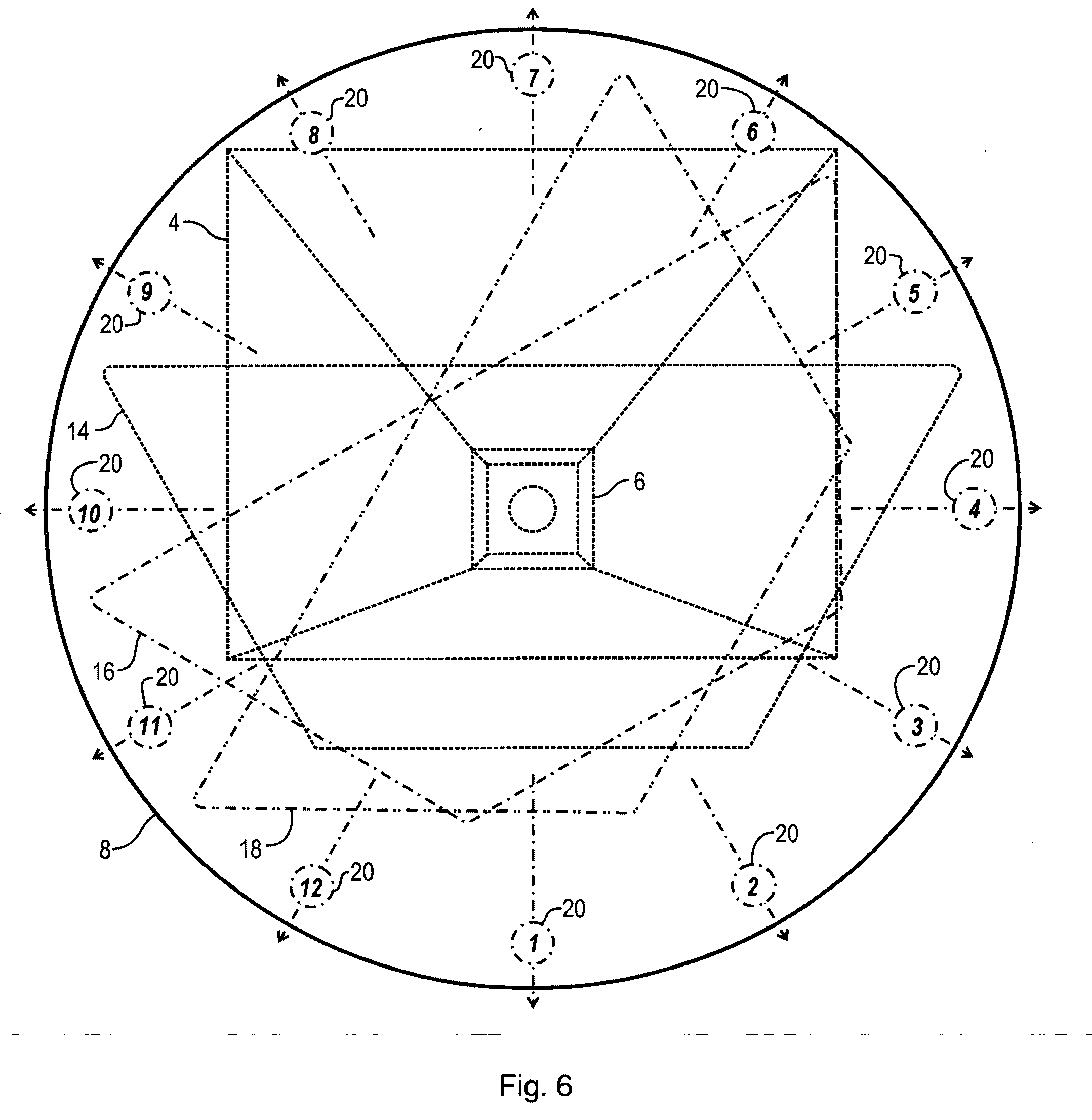
[0052] An illustrative embodiment of the present invention is a shelf mounted indoor TV antenna designed to receive broadcast high-definition television (“HDTV”). A log periodic antenna structure is tuned and impedance matched to receive the UHF TV band, which are principally TV channels 14 through 69. The antenna structure rotates within a statio...


PUM


Abstract

An antenna system for receiving radio waves and for operation in conjunction with a remote controller that transmits control data including gain state data. The antenna system includes an antenna that receives the radio waves and outputs a radio frequency signal and a radio frequency amplifier coupled to receive and amplify the radio frequency signal to a gain level controlled through a gain control input. A remote control receiver receives the control data and a controller is coupled to the gain control input and the remote control receiver. The controller couples the gain state data to the gain control input, thereby remotely controlling the gain level of the radio frequency amplifier. A remotely controlled antenna rotor is also taught.

Description

BACKGROUND OF THE INVENTION [0001] 1. Field of the Invention [0002] The present invention relates to antennas. More specifically, the present invention relates to remotely controlled television antennas with channel memory and having a programmable gain amplifier and a remotely controlled antenna rotor. [0003] 2. Description of the Related Art [0004] Television viewing is ubiquitous in modern society. Users access television program content though radio broadcast signals, cable, satellite, and prerecorded media. While cable, satellite and prerecorded media offer excellent performance in terms of video and audio quality, they all require some payment of ongoing services fees or a purchase price. Broadcast television is unique in that it is typically accessible without recurring charges. However, broadcast television service is disadvantaged by the vagaries of radio wave propagation. It is a common collective experience of users to deal with antenna and tuning issues in seeking clear ...

Claims


Application Information

Patent Timeline
IPC IPC(8): H04L27/00
CPCH01Q3/02H03G1/02H01Q11/10
Inventor LAM, ALAN MAN LUNG
Owner GENERAL WIRELESS OPERATIONS
Why Eureka
Try Eureka