Fixing device
a technology of fixing device and fixing surface, which is applied in the direction of electrographic process, electric/magnetic/electromagnetic heating, instruments, etc., can solve the problems of excessive rise in drop in temperature of paper passage area, abnormal etc., to prevent excessive temperature of paper non-passage area
- Summary
- Abstract
- Description
- Claims
- Application Information
AI Technical Summary
Benefits of technology
Problems solved by technology
Method used
Image
Examples
embodiment 1
[0051]FIG. 3 is a schematic cross-sectional view showing the overall configuration of an image forming apparatus suitable for incorporation of a fixing apparatus according to Embodiment 1 of the present invention.
[0052] As shown in FIG. 3, an image forming apparatus 100 has an electrophotographic photosensitive body (hereinafter referred to as “photosensitive drum”) 101, an electrifier 102, a laser beam scanner 103, a developing unit 105, a paper feed apparatus 107, a fixing apparatus 200, a cleaning apparatus 113, and so forth.
[0053] In FIG. 3, photosensitive drum 101 is rotated at a predetermined peripheral velocity in the direction indicated by the arrow while its surface is uniformly charged to a negative predetermined dark potential V0 by electrifier 102.
[0054] Laser beam scanner 103 outputs a laser beam 104 modulated in accordance with a time series electrical digital pixel signal of image information input from a host apparatus such as an image reading apparatus or compute...
embodiment 2
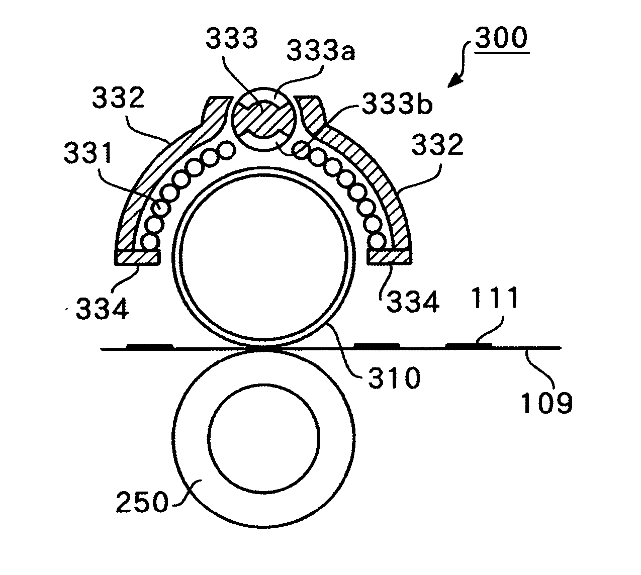
[0095] Next, the configuration of distinctive parts of a fixing apparatus according to Embodiment 2 will be described. FIG. 9 is a schematic cross-sectional view showing the configuration of a fixing apparatus according to Embodiment 2. As shown in FIG. 9, in this fixing apparatus 700 the magnetism suppressing elements are configured as magnetism masking members 701a and 701b, while the rest of the configuration is similar to that of fixing apparatus 300 according to Embodiment 1.
[0096] Magnetism masking members 701a and 701b serving as magnetism suppressing elements are formed of a material that can mask magnetic coupling between center core 333 and heat-producing roller 310 corresponding to paper non-passage areas of heat-producing roller 310—for example, an inexpensive, low-permeability electrical conductor such as copper or aluminum. As shown in FIG. 9 and FIG. 10, these magnetism masking members 701a and 701b are provided opposite each other in the peripheral surface of center...
embodiment 3
[0109] Next, the configuration of a fixing apparatus according to Embodiment 3 will be described. FIG. 13 is a schematic cross-sectional view showing the configuration of a fixing apparatus according to Embodiment 3. As shown in FIG. 13, in this fixing apparatus 1100 a bypass path section 332a forming a magnetic flux path is formed so as to circumvent center core 333 on the side opposite heat-producing roller 310 in arch core 332 covering exciting coil 331 with center core 333 between. The rest of the configuration of this fixing apparatus 1100 is similar to that of fixing apparatus 700 according to Embodiment 2.
[0110] In this fixing apparatus 1100, in addition to a magnetic flux path whose degree of magnetic coupling is regulated by magnetism masking members 701a and 701b serving as magnetism suppressing elements formed in center core 333, a new magnetic flux path is formed by bypass path section 332a of arch core 332.
[0111] Thus, in this fixing apparatus 1100 a new path can be s...
PUM
 Abstract
Description
Claims
Application Information
 - R&D
- Intellectual Property
- Life Sciences
- Materials
- Tech Scout
- Unparalleled Data Quality
- Higher Quality Content
- 60% Fewer Hallucinations
Browse by: Latest US Patents, China's latest patents, Technical Efficacy Thesaurus, Application Domain, Technology Topic, Popular Technical Reports.
© 2025 PatSnap. All rights reserved.Legal|Privacy policy|Modern Slavery Act Transparency Statement|Sitemap|About US| Contact US: help@patsnap.com


