Lithotripsy method and system without patient relocation between diagnostic imaging and treatment

a lithotripsy and patient technology, applied in the field of lithotripsy system, can solve problems such as patient injury, and achieve the effect of sufficient patient access

Inactive Publication Date: 2007-01-18
SIEMENS AKTIENGENELLSCHAFT
View PDF6 Cites 11 Cited by
  • Summary
  • Abstract
  • Description
  • Claims
  • Application Information

AI Technical Summary

Benefits of technology

[0011] Because the patient is not repositioned between the first step and the second step, several advantages are achieved: the position of internal organs and of the calculus in the patient do not change. The generated 3D image data set of the patient that serves for diagnosis of the calculus additionally gives information about the exact position of the calculus. Given the actual stone destruction in the second step, no further x-ray exposure of the patient thus needs to ensue. Locating of the stone location can be implemented directly using the 3D image data set. Diagnosis and destruction are equally completed in a single step.
[0012] No new x-ray location of the calculus thus is necessary for the shockwave lithotripsy. The patient is only exposed to x-ray radiation once, namely in the first step. The advantage for the workflow in a hospital or a medical practice is that accommodations, personnel and apparatuses must only be scheduled for a single treatment date in which both steps are executed. The patient must only keep a single appointment.
[0013] The apparatus coordinate systems that apply for the generation of the 3D image data set and the lithotripsy system can easily be matched to one another or can be registered to one another via known measures. For example, it is thus possible to mechanically securely couple an x-ray system suitable for generation of the 3D data set to a shockwave system and to align these relative to one another. Alternatively or additionally, commercially available 3D positioning systems can be used in order to determine the mutual position of 3D x-ray system and shockwave system and to correlate their apparatus coordinate systems with one another. In such a case a mobile x-ray apparatus can also be used that can be removed from the patient or the treatment area around the patient after generation of the 3D image data set in order to achieve sufficient access to the patient during the lithotripsy.

Problems solved by technology

If such shockwaves are inaccurately targeted at the calculus, this can lead to injury of the patient such as, for example, a kidney hematoma in the case of a kidney lithotripsy.
This procedure exhibits various disadvantages: two separate procedures, namely the diagnosis exam and the lithotripsy, must be administered in the workflow of a medical practice or clinic.

Method used


Image

  • Lithotripsy method and system without patient relocation between diagnostic imaging and treatment
  • Lithotripsy method and system without patient relocation between diagnostic imaging and treatment

Examples


Embodiment Construction

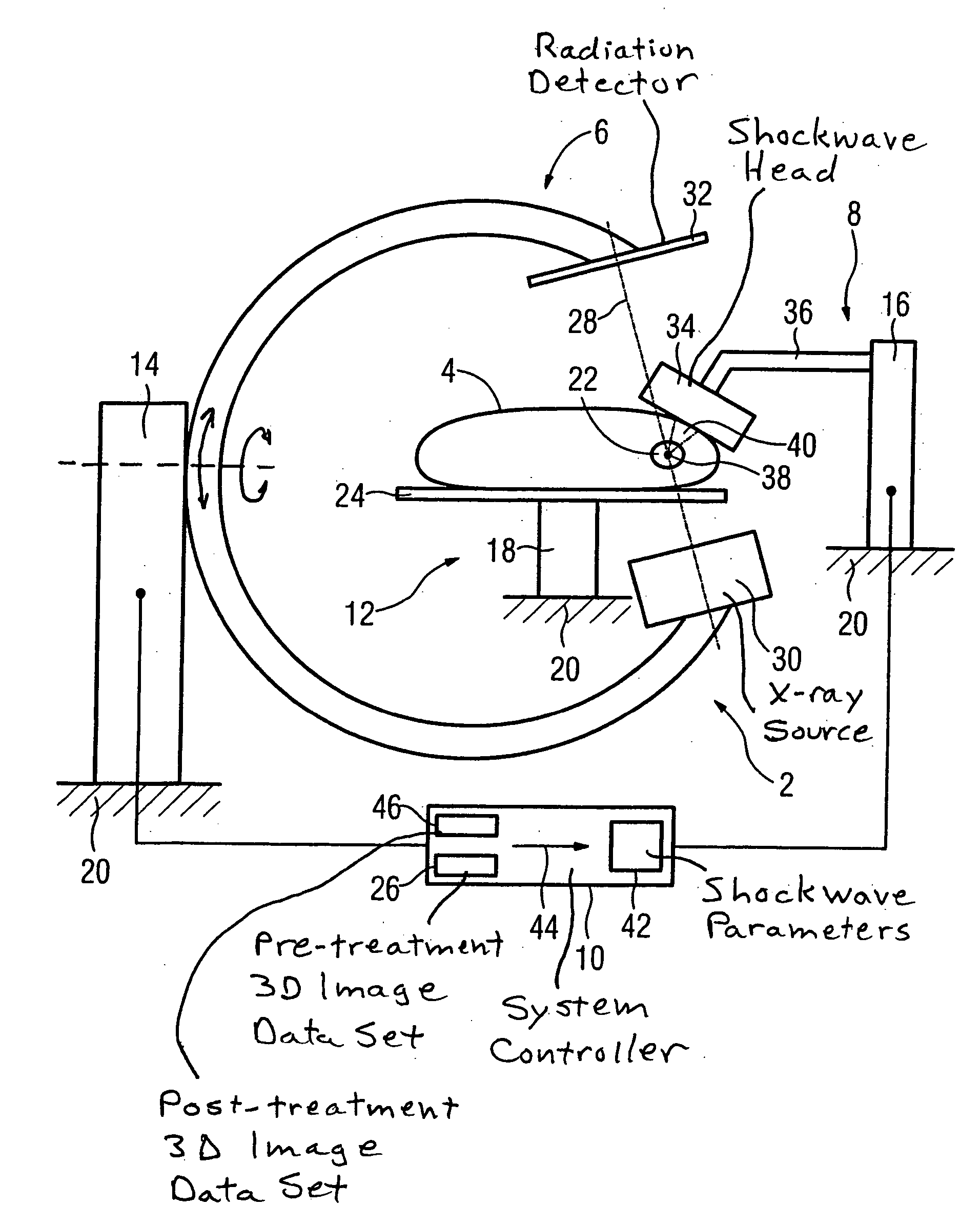
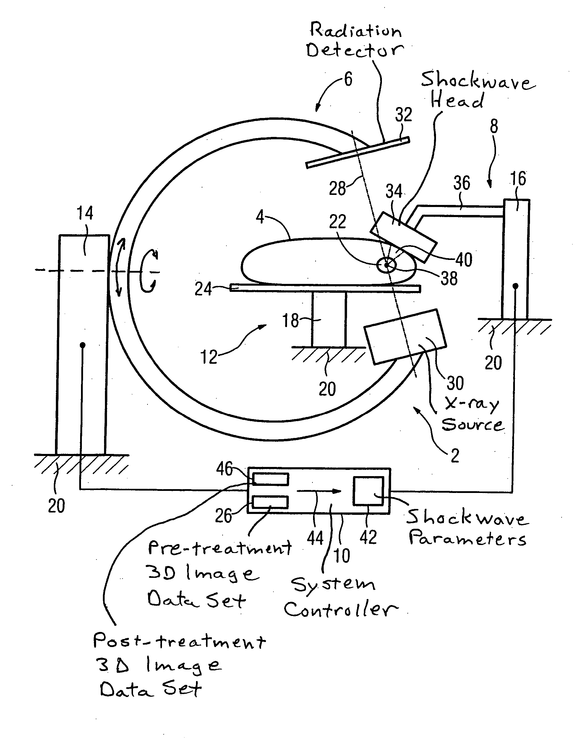
[0024] The FIGURE shows a lithotripsy system 2 with a patient 4. The lithotripsy system 2 has a 3D x-ray apparatus 6, a shockwave system 8 and a patient table 12 which are permanently connected to the floor 20 of a treatment room (not shown) via respective bases 14 and 18, and are thus arranged in a fixed spatial relation to one another. The 3D x-ray apparatus 6 and shockwave system 8 are connected via a system controller 10. Due to the known spatial association of the apparatuses relative to one another, the spatial position of all components of the lithotripsy system 2 in their apparatus frame of reference is known to the system controller 10 at every point in time. Alternatively, a movable system can be used with components that are situated in a known spatiail relation to one another.

[0025] The treatment situation shown in the FIGURE has the following case history. The patient 4 has had pain in the abdomen for two weeks. Ten days ago he visited his primary care physician (not s...


PUM


Abstract

In a method to disintegrate a calculus in a patient by shockwave lithotripsy, a 3D image data set of the patient is generated in a first step; the shockwave lithotripsy is conducted in a second step; and first step and second step are conducted with an unchanged position of the patient. A lithotripsy system to disintegrate a calculus in a patient has a shockwave system to disintegrate the calculus and a 3D imaging system to generate a 3D image data set of the patient without movement of the patient.

Description

BACKGROUND OF THE INVENTION [0001] 1. Field of the Invention [0002] The invention concerns a method and a lithotripsy system used to disintegrate a calculus in a patient, normally living people or animals. [0003] 2. Description of the Prior Art [0004] Lithotripsy systems are used to disintegrate calculi such as, for example, kidney, bladder, ureter or gall stones. The destruction of the calculus inside the patient ensues in shockwave lithotripsy by ultrasound shockwaves that are emitted by a shockwave head of a lithotripsy system, normally tapering conically and being concentrated at a focal point. [0005] The main task of lithotripsy is to place the focal point of the ultrasonic shockwave as exactly as possible in the center of the calculus to be disintegrated or one of its fragments. The energy application inside the calculus is thus no more than that which leads to the best possible destruction thereof. This also protects the patient as well as possible from unwanted side effects,...

Claims


Application Information

Patent Timeline
Patent Type & Authority Applications(United States)
IPC IPC(8): A61H1/00
CPCA61B6/12A61B6/4441A61B2019/5238A61B17/2255A61B17/2256A61B6/466A61B2090/376
Inventor BUCHHOLTZ, GERHARDFEHRE, JENSGRANZ, BERNDHOHEISEL, MARTINKRUFT, WERNERLANSKI, MARKUSMAHLER, MATTHIASMEINERT, CHRISTIANMERTELMEIER, THOMASNANKE, RALFRATTNER, MANFRED
Owner SIEMENS AKTIENGENELLSCHAFT
Why Eureka
Try Eureka