Wear tester

a technology of wear and measurement device, applied in the direction of measuring device, material strength using repeated/pulse force, instruments, etc., can solve the problem of wear presen

Inactive Publication Date: 2007-01-25
MTS SYSTEMS CORPORATION
View PDF9 Cites 10 Cited by
  • Summary
  • Abstract
  • Description
  • Claims
  • Application Information

AI Technical Summary

Benefits of technology

[0005] This Summary and the Abstract are provided to introduce some concepts in a simplified form that are further described below in the Detailed Description. The Summary and Abstract are not intended to identify key features or essential features of the claimed subject matter, nor is it intended to be used as an aid in determining the scope of the claimed subject matter. In addition, the description herein provided and the claimed subject matter should not be interpreted as being directed to addressing any of the short-comings discussed in the Background.
[0006] A first aspect of the invention is a test assembly structure having a first specimen support, a displacement mechanism joined to the first specimen support and a second specimen support. A loading assembly is joined to the second specimen support and configured so as to engage a specimen held by the second specimen support with a specimen held by the first specimen support. A self-reacting structure is joined to the loading

Problems solved by technology

The attachment of the blades to the shaft are dynami

Method used


Image

  • Wear tester
  • Wear tester
  • Wear tester

Examples


Embodiment Construction

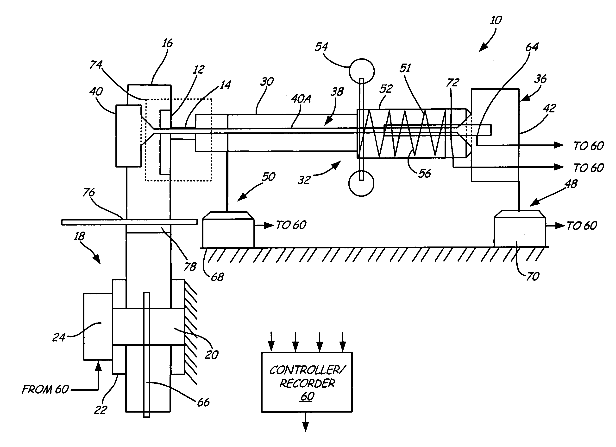
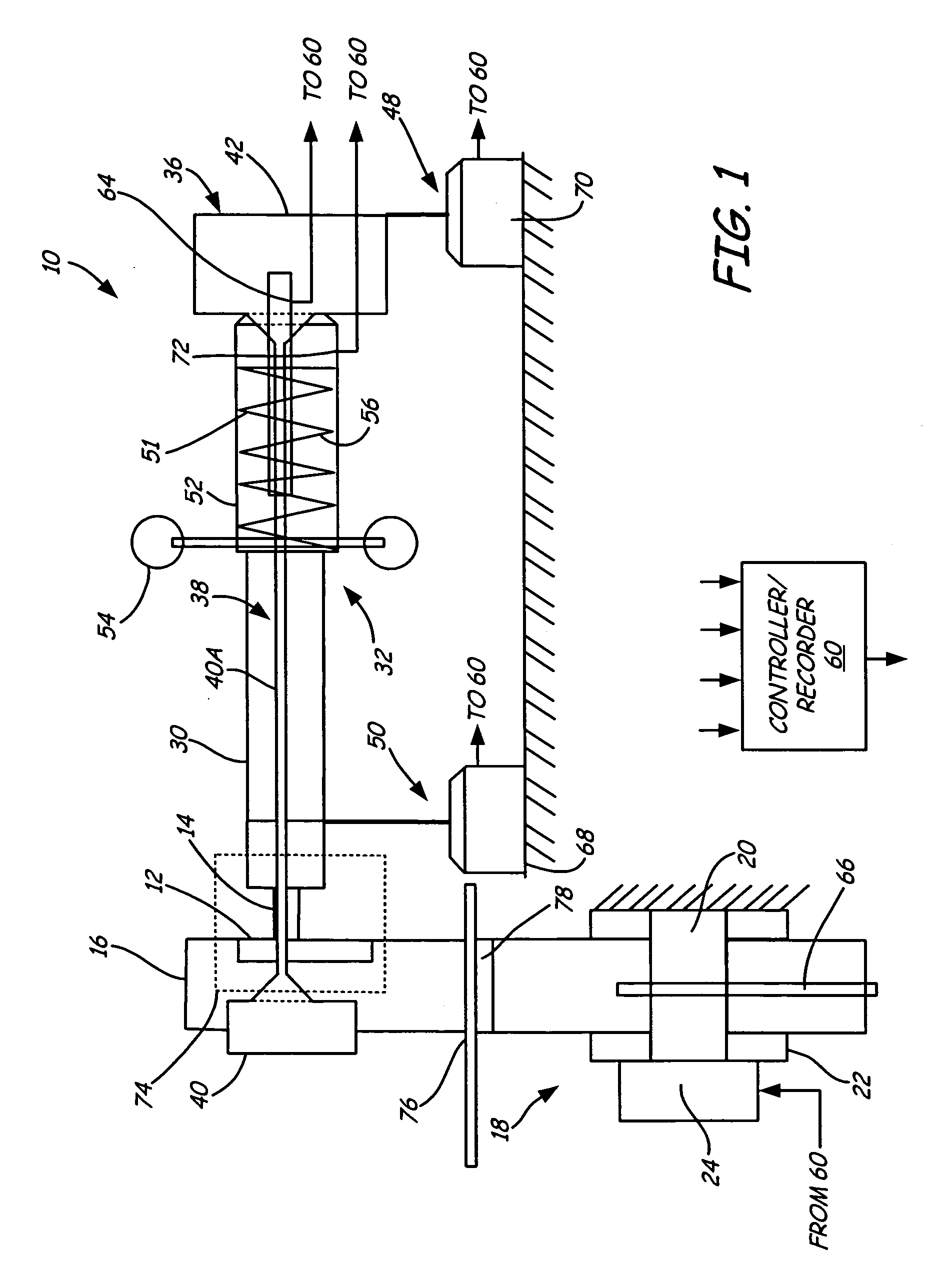
[0014] A wear tester system structure 10 is illustrated in FIG. 1 and is used to simulate, cause and / or characterize wear occurring between two specimens 12, 14. Specimen 12 is mounted to an axial specimen holder 16 that in turn is joined to a displacement assembly 18, herein exemplified as an actuator assembly. Actuator assembly 18 includes a piston 20 moveable in a cylinder 22 under the control of a servo valve 24. As appreciated by those skilled in the art, other forms of displacement assemblies such as other forms of actuator assemblies (e.g. electric, pneumatic, hydraulic, etc.) can be used.

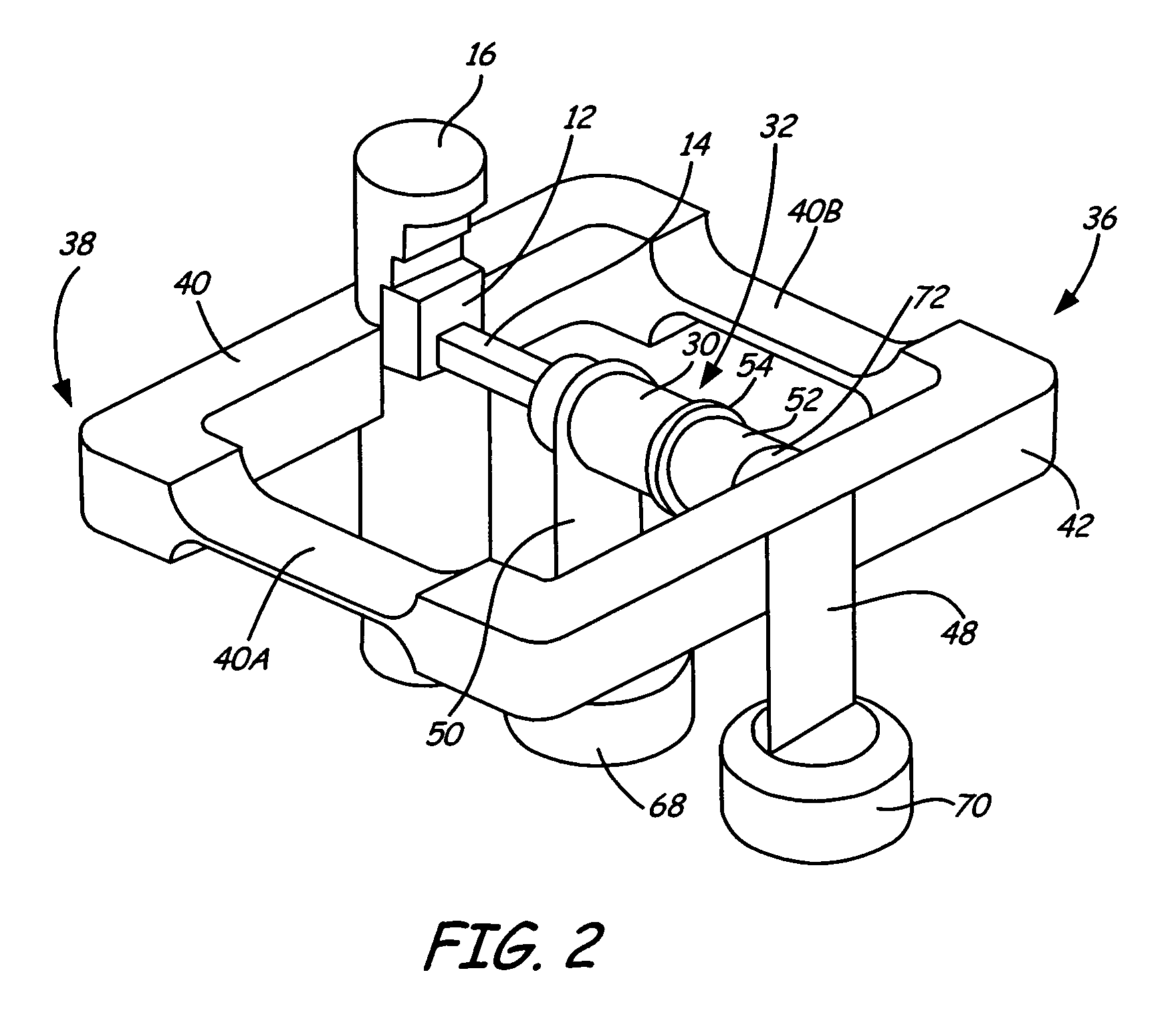
[0015] Specimen 14 likewise is mounted to a specimen holder 30 that in turn is joined to a loading assembly 32. Typically, specimen 14, specimen holder 30 and loading assembly 32 are oriented in so as to apply a force that is normal to axial displacement of specimen 12, although other orientations can be used. Referring also to FIG. 2, loading assembly 32 is mounted to member 36 so as to pr...


PUM


Abstract

A test assembly structure having a first specimen support, a displacement mechanism joined to the first specimen support and a second specimen support. A loading assembly is joined to the second specimen support and configured so as to engage a specimen held by the second specimen support with a specimen held by the first specimen support. A self-reacting structure is joined to the loading assembly having a flexure substantially rigid in the direction of loading of the loading assembly and substantially compliant in the direction of displacement of the displacement mechanism. A second flexure can be configured to support the second specimen support and/or loading assembly on a base. The second flexure is substantially compliant in the direction of loading of the loading assembly and substantially rigid in the direction of displacement of the displacement mechanism.

Description

CROSS-REFERENCE TO RELATED APPLICATION [0001] The present application is based on and claims the benefit of U.S. provisional patent application Ser. No. 60 / 701,579, filed Jul. 22, 2005, the content of which is hereby incorporated by reference in its entirety.BACKGROUND OF THE INVENTION [0002] The discussion below is merely provided for general background information and is not intended to be used as an aid in determining the scope of the claimed subject matter. [0003] Wear and fretting fatigue are phenomenon often prompted or caused by high frequency, low amplitude friction motion, which is typical in clamped joints and closely fitted components. Fretting fatigue is defined as the debit in fatigue for example due to early fatigue cracking initiation resulting from near surface stress risers developed from surface rubbing. [0004] For instance, in one wear / fretting application, turbine blades are attached to a rotating shaft. The blades experience centrifugal forces as they rotate as ...

Claims


Application Information

Patent Timeline
IPC IPC(8): G01N3/02
CPCG01N3/02G01N3/32G01N3/56G01N2203/0005G01N2203/0073G01N2203/0023G01N2203/0028G01N2203/0048G01N2203/0017
Inventor BUSHEY, JOHN A.CHRISTOPHERSON, JASON A.HAEG, STEVEN R.
Owner MTS SYSTEMS CORPORATION
Why Eureka
Try Eureka