Surface features in microprocess technology

a microprocessing and surface feature technology, applied in the field of microchannel apparatus, can solve the problem that the diffusion alone would likely be insufficient for the reacting molecules to hit the active catalyst wall, and achieve the effect of enhancing unit operation and performan

Active Publication Date: 2007-01-25
VELOCYS CORPORATION
View PDF13 Cites 127 Cited by
  • Summary
  • Abstract
  • Description
  • Claims
  • Application Information

AI Technical Summary

Benefits of technology

[0024] In the present invention, surface features in microchannels can be used to enhance unit operations as the Reynolds number is increased. In the invention, the surface features can be advantageously employed at Re of 100 or more, in some embodiments Re is 200 or more, 1000 or more. and in some embodiments Re is in the range of 300 to 2200. Further, the use of surface features offers additional surprising enhancement in the turbulent regime as well.
[0025] An important element in many aspects of the present invention is the interaction of fluid molecules with an “active surface.” A surface is considered active if either mass or heat is exchanged at the surface. The surface is inclusive of the floor and sides of the grooves as well as the ridges between features. A “ridge” is a wall or the surface that connects at least two open surface features and is open to the main flow channel. As the number of interactions of the fluid with the active surface is increased, the performance of the unit operation is further enhanced. For the case of a chemical reactor, a heterogeneous catalyst may be disposed within the surface features as well as on the tops or ridges or flat regions of the microchannel and optionally along all surfaces or selected surfaces. Rather than diffusion as the sole driving force for movement of the reacting species to the active wall, advection or flow convection becomes a dominant driving force for quickly moving reactants to the catalytic wall and removing products from the wall to the bulk flow stream. As an example, if diffusion alone is the dominant driving force for moving flow from the bulk to the active catalyst wall, a characteristic time may be on the order of a few to tens of milliseconds for gaseous chemical reactors that operate with an overall contact time of a few to tens of milliseconds. For a stream of methane and air in a 1 mm channel at 850 C and 1.0 bar the diffusivity is about 2.2 cmˆ2 / sec and the diffusion distance from the center of the channel gap (assuming that catalyst is disposed in active surface features on both sides of the microchannel gap) is about 0.5 mm. The resulting characteristic time for diffusion is on the order of 1 millisecond.

Problems solved by technology

Thus diffusion alone would likely be insufficient for those reacting molecules to hit the active catalyst wall.

Method used


Image

  • Surface features in microprocess technology
  • Surface features in microprocess technology
  • Surface features in microprocess technology

Examples


examples

Steam Methane Reforming Reactions in Microreactors with Wall Surface Features

[0177] The effect of surface features on the reactor performance was explored for the methane steam reforming reaction. The intent of the features was to increase the conversion per length, especially at low catalyst activity. The surface features increase the available surface area for catalyst, they allow a solution derived catalyst to be washcoated uniformly, and they reduce external mass transport limitations in the bulk microchannel and thus allow the reactor to operate closer to the intrinsic potential of the catalyst activity.

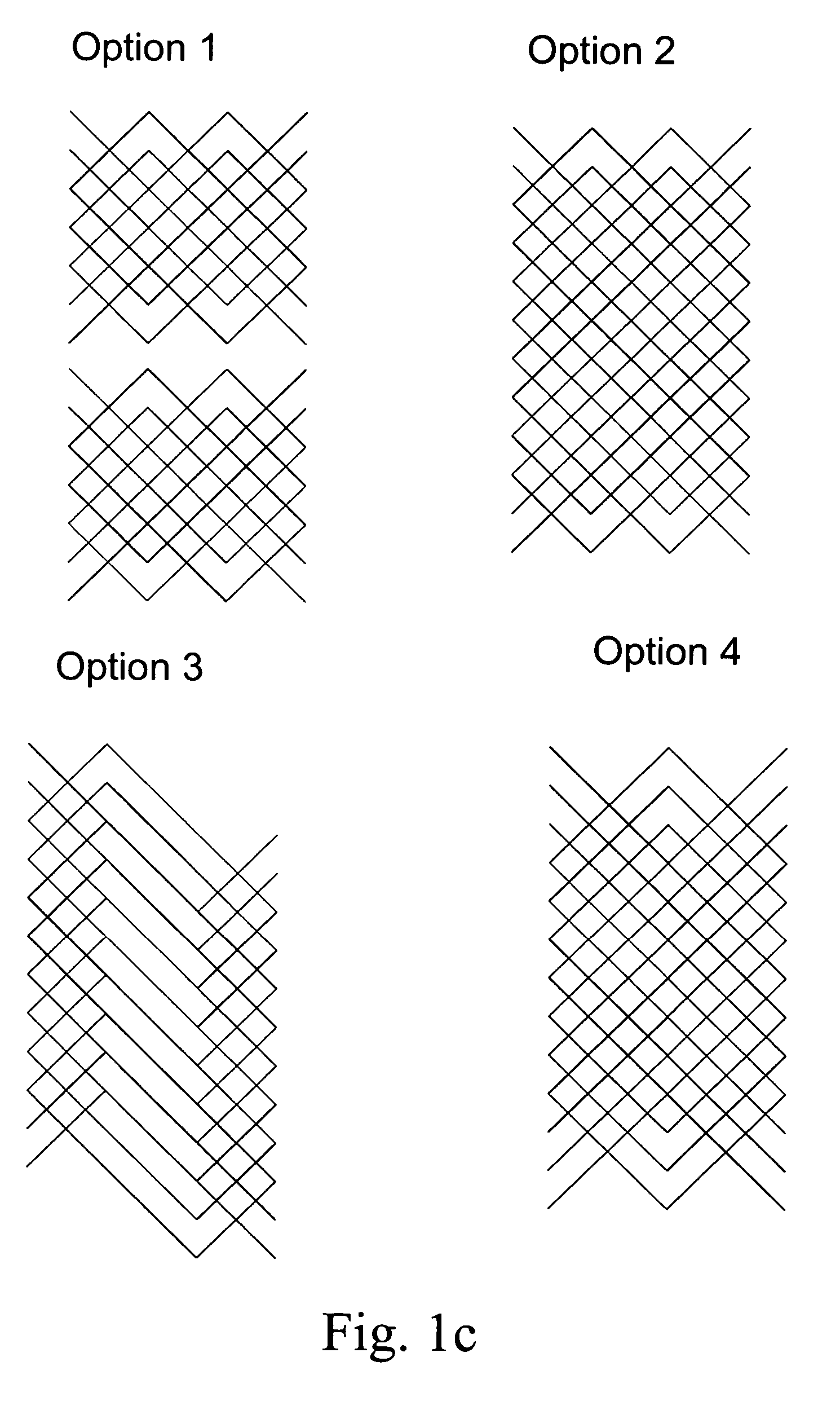
[0178] In this example, the surface features have rectangular cross section shape; are on either one or both sides of the microchannel; the depth of the surface features are of the same order as the main flow channel gap; and the surface features are placed at a specified angle relative to the main flow direction

Part of the dimensions defining the problems are kept the same...

examples b and c

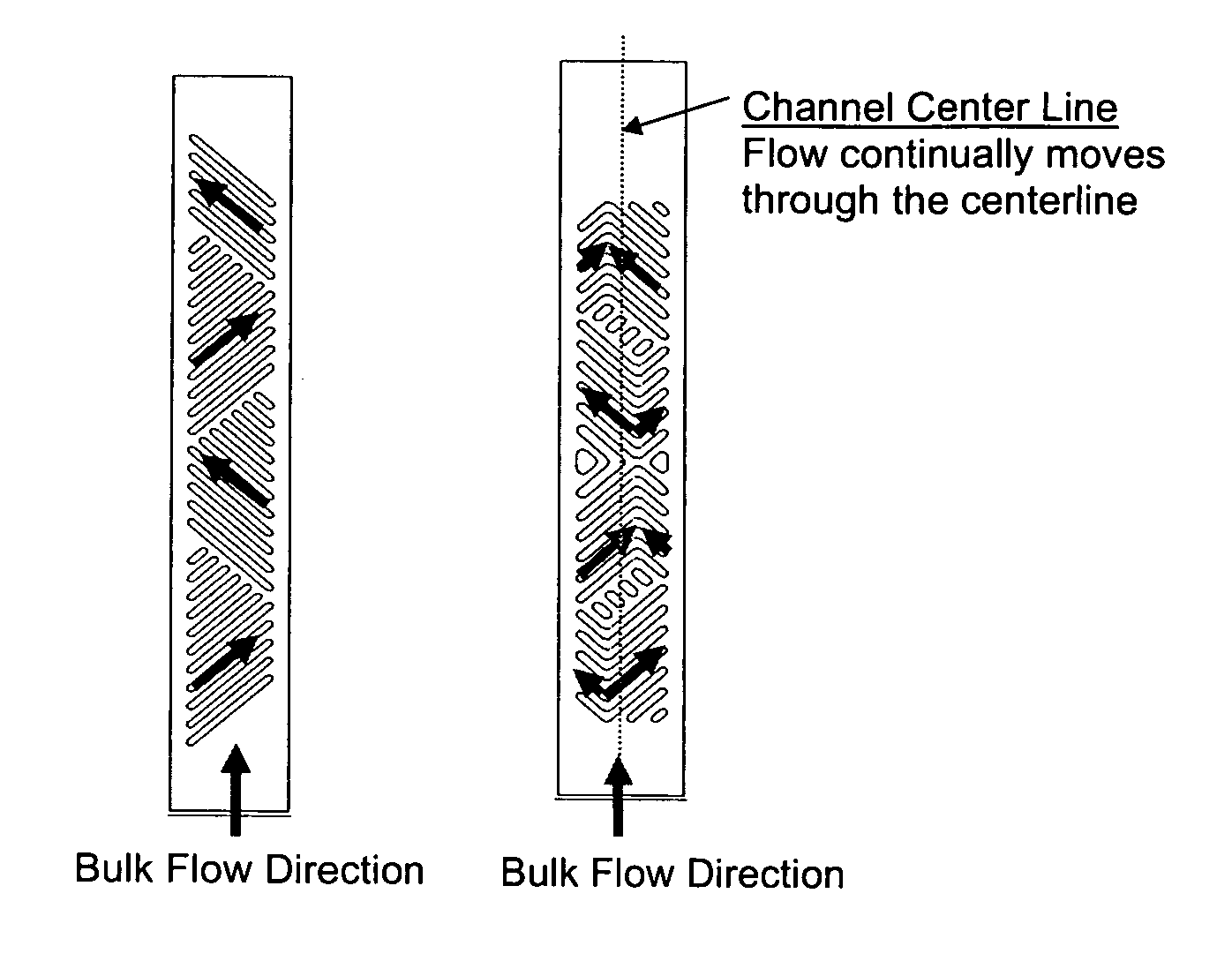
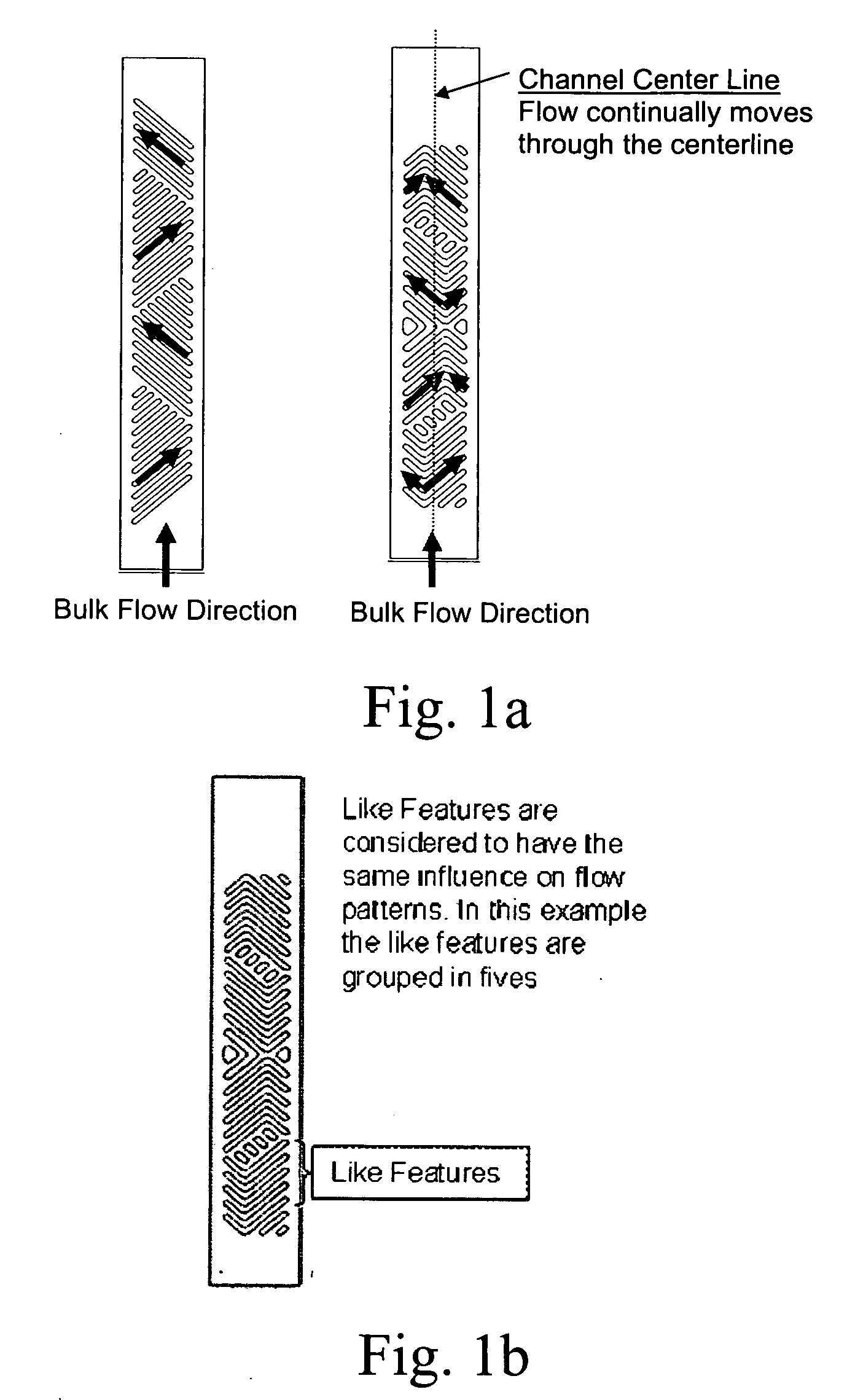
In examples B and C, mirror image surface features in terms of shape and orientation were present on opposite walls of the channel. In this example, grooves of type B are imposed on one wall, and grooves of type C are imposed on the opposite wall (opposing angles). This orientation is also referred to as a trans configuration. The plane of symmetry at the middle of the channel is lost.

[0201] The dominant flows within the surface features on the opposite walls point to opposite directions transverse-wise. On one side, the flow turns from the edge close to the center of the main flow channel to the farther edge. While on the opposite side, the flow turns from the edge farther away from the center of the main flow channel to the edge close to the center of the flow channel. These flow patterns within the surface grooves lead to no dominant transverse flow direction in the main flow channel. This is quite distinct from the presence of dominant flow directions in case B (the flow points ...

case 1

Inch Channel Gap

Using liquid water as the fluid:

Boundary Conditions [0236] Operating pressure=14.7 psi [0237] Outlet pressure=0 psig [0238] Inlet velocity=1.54 m / s [0239] Inlet temperature=300 K [0240] Wall temperature=350 K

The Reynolds number of the fluid in the channel was 1000. The Reynolds number was calculated as Re=ρ⁢ ⁢vDμ

where [0241]ρ=density of fluid, kg / m3 [0242] v=Velocity of fluid, m / s [0243] D=Hydraulic diameter of channel, m [0244]μ=Viscosity of fluid, kg / m / s

The overall heat transfer coefficient was estimated as HTCoverall=Q.wallAflat⁡(LMTD)

where [0245] HTCoverall=Overall heat transfer coefficient (W / m2 / K) [0246] Qwall=Heat transferred from wall (W) [0247] Aflat=Heat transfer area based on smooth (or no surface feature) geometry, m2 [0248] LMTD=Log mean temperature difference

Model Chosen

K-Omega model (SST type) was chosen for CFD analysis. The values of model constants were default values provided by Fluent 6.0. Full multi-component diffusion species tran...


PUM

PropertyMeasurementUnit
lengthaaaaaaaaaa
contact timeaaaaaaaaaa
Reynolds numbersaaaaaaaaaa

Abstract

This invention relates to microchannel apparatus that includes microchannels with interior surface features for modifying flow; processes utilizing this microchannel architecture, and methods of making apparatus having these features.

Description

RELATED APPLICATIONS [0001] This application is a continuation-in-part of U.S. patent application Ser. No. 11 / 089,440 filed 23 Mar. 2005. Also, in accordance with 35 U.S.C. sect. 119(e), this application claims priority to U.S. Provisional Applications Nos. 60 / 697,900 filed 8 Jul. 2005, 60 / 727,126 filed 13 Oct. 2005 and 60 / 731,596 filed 27 Oct. 2005.FIELD OF THE INVENTION [0002] This invention relates to microchannel apparatus that includes microchannels with interior surface features for modifying flow; processes utilizing this microchannel architecture, and methods of making apparatus having these features. INTRODUCTION [0003] In recent years there has been tremendous academic and commercial interest in microchannel devices. This interest has arisen due to the advantages from microtechnology including reduced size, increased productivity, the ability to size systems of any desired capacity (i.e., “number-up” channels), increased heat transfer, and increased mass transfer. A review...

Claims


Application Information

Patent Timeline
Patent Type & Authority Applications(United States)
IPC IPC(8): B32B37/00
CPCB01F5/0611Y10T156/1093B01F2005/0621B01F2005/0636B01J19/0093B01J23/464B01J35/04B01J2219/00822B01J2219/00824B01J2219/00835B01J2219/0086B01J2219/00873B01J2219/00889B01J2219/00961B01L3/5027B01F13/0059Y10T137/2224B01F25/4311B01F25/4317B01F25/431971B01F33/30
Inventor TONKOVICH, ANNA LEEYANG, BINPERRY, STEVEN T.FITZGERALD, SEAN P.ARORA, RAVIJAROSCH, KAIYUSCHAK, THOMAS D.FANELLI, MADDALENASULLIVAN, TIMMASANEC, TERRY
Owner VELOCYS CORPORATION
Why Eureka
Try Eureka