Wet clutch friction plate and method

a technology of friction plate and wet clutch, which is applied in the field of friction plate, can solve the problems of increasing the radius, adding size and cost to the assembly, and difficult to keep the center of the larger friction facing layer at an acceptable temperature level, so as to improve the performance of increase the lubrication, and effectively cool the wet clutch system

Inactive Publication Date: 2007-01-25
GM GLOBAL TECH OPERATIONS LLC
View PDF4 Cites 21 Cited by
  • Summary
  • Abstract
  • Description
  • Claims
  • Application Information

AI Technical Summary

Benefits of technology

[0004] The present invention provides a friction plate with increased lubrication to effectively cool a wet clutch system during clutch engagement. T

Problems solved by technology

However, this increase in radius adds size and cost to the assembly, and may require additional cooling oil to be transferred across the plates for cooling.
It may be difficult to keep the cen

Method used


Image

  • Wet clutch friction plate and method
  • Wet clutch friction plate and method
  • Wet clutch friction plate and method

Examples


Embodiment Construction

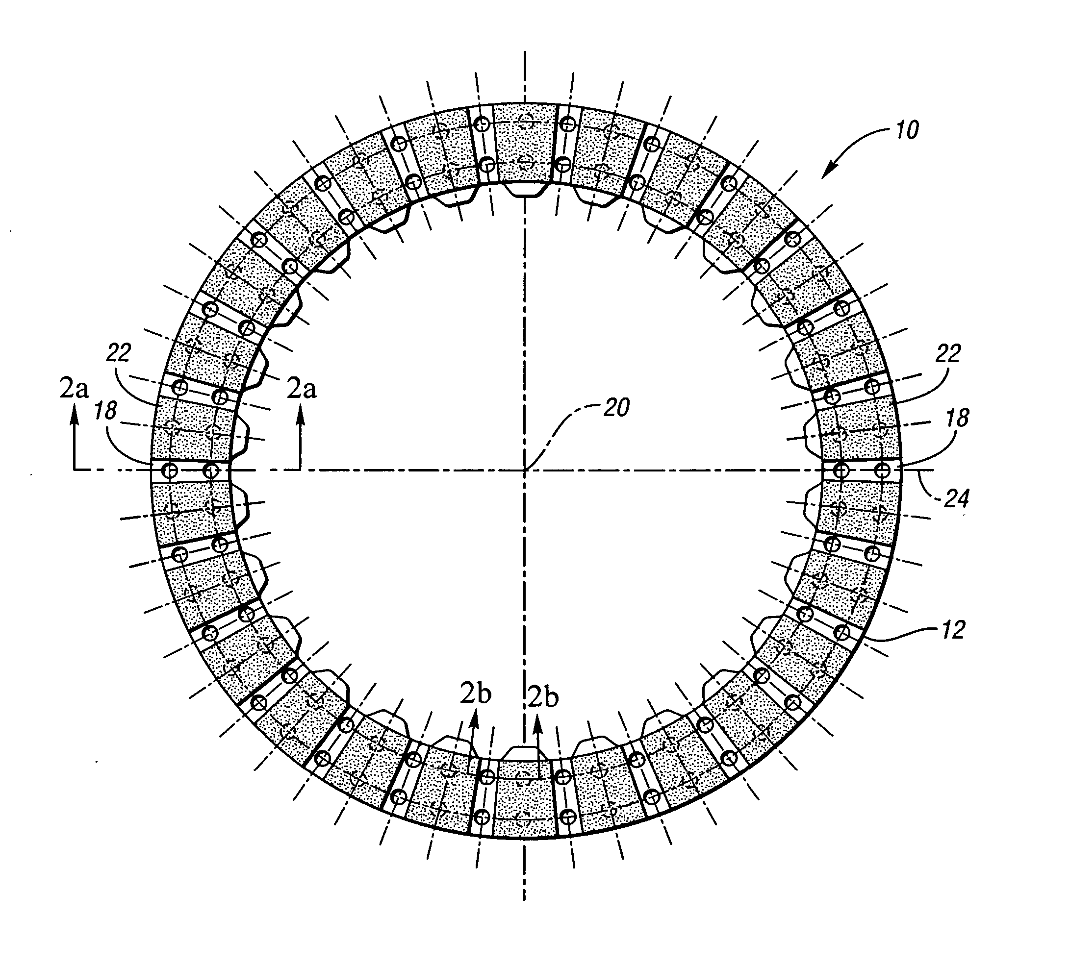
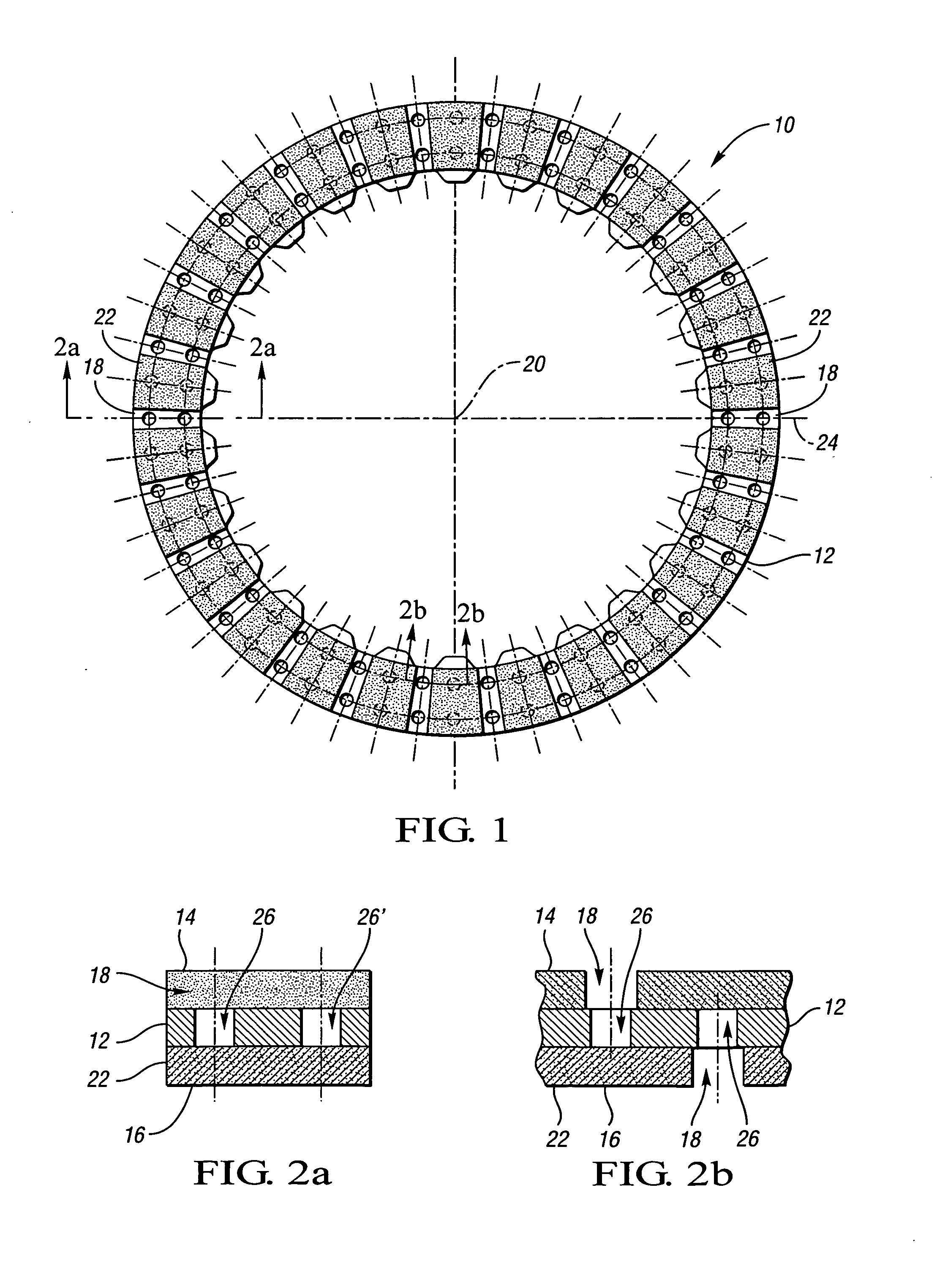
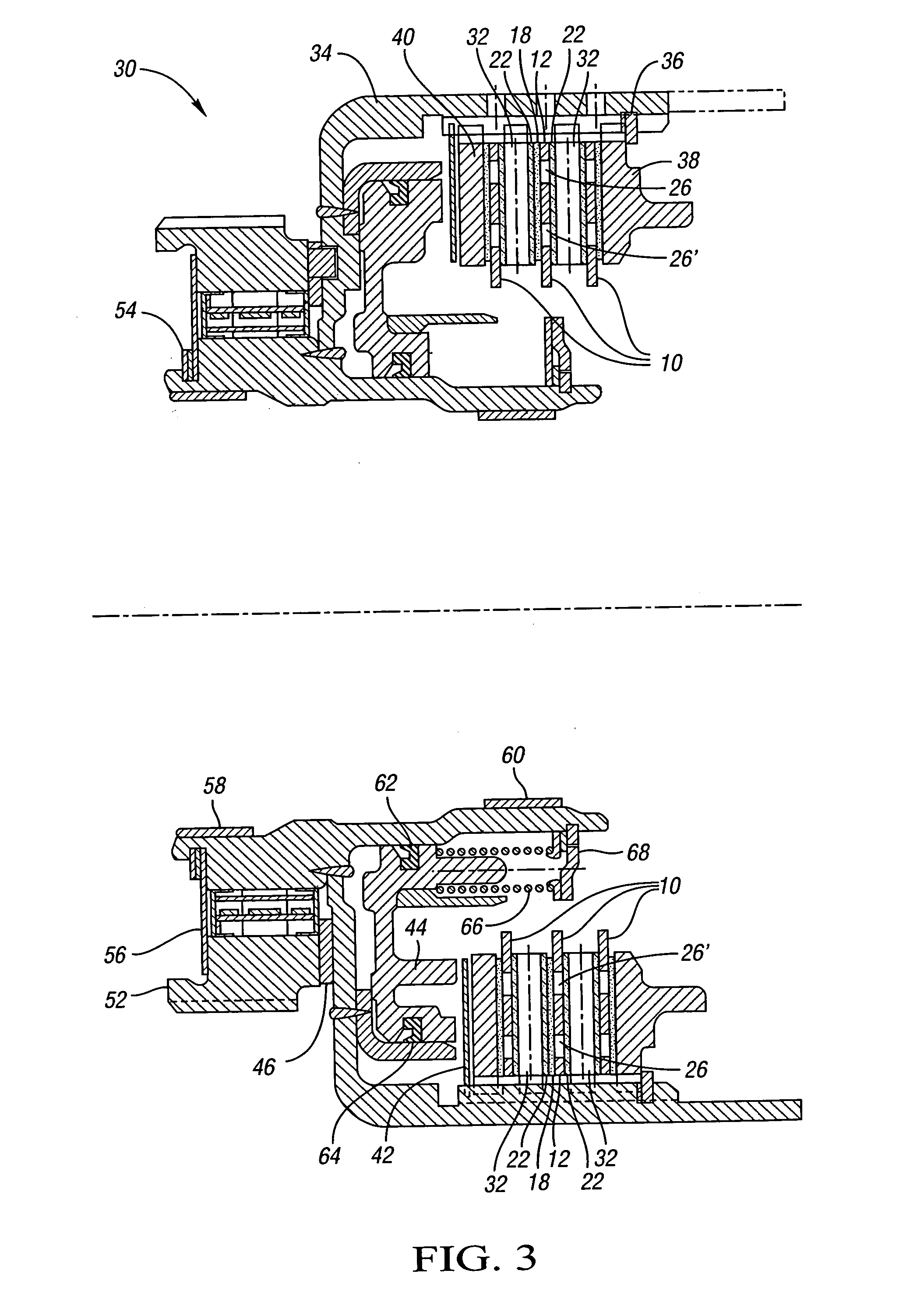
[0014]FIG. 1 illustrates an exemplary friction plate 10 for use in a wet clutch system consistent with the present invention. The friction plate 10 has a core plate 12 with a first friction facing layer 14 and a second friction facing layer 16 attached thereto, both of which are shown in FIG. 2. The friction facing layers 14 and 16 are each disposed on an opposite face of the core plate 12. The preferred material for the friction facing layers 14 and 16 will have sufficient porosity to allow fluid flow within the friction facing layers 14 and 16, such as woven carbon fiber. The core plate 12 must be of sufficient rigidity to provide support for the friction facing layers 14 and 16 during clutch engagements. Preferably, the core plate 12 will be formed from steel.

[0015] Each of the friction facing layers 14 and 16 will have a plurality of radially oriented lubrication grooves 18 disposed circumferentially with respect to the center of rotation 20 of the friction plate 10. The plural...


PUM


Abstract

The present invention provides a friction plate with features to provide additional cooling for use within a wet clutch system. The friction plate has a core plate with a friction facing layer affixed to each face of the core plate. The first friction facing layer has a plurality of radially oriented lubrication grooves formed by a plurality of friction pads having porosity. Additionally, the second friction facing layer has a plurality of friction pads formed by radially oriented lubrication grooves whose centerline is coincident with the radial centerline of the friction pads of the first friction facing layer. Each of the lubrication grooves has at least one hole provided therein to introduce fluid to effect cooling of the friction pad opposite the groove. Additionally, the present invention provides a method of enhancing the performance of a wet clutch system.

Description

TECHNICAL FIELD [0001] The present invention relates to a friction plate with increased lubrication capability for use within a wet clutch system. BACKGROUND OF THE INVENTION [0002] In a wet clutch system for an automatic transmission, friction plates and reaction plates are typically alternately stacked or interleaved. The friction plates are typically splined at an inner periphery, and the reaction plates are splined at an outer periphery. Accordingly, when the plates are compressed together, frictional engagement between the friction and reaction plates cause the plates to rotate together, thereby transmitting torque between the inner and outer splined interfaces of the plates. The wet clutch is bathed in transmission fluid during operation. This fluid serves as a lubricant as well as a cooling means to dissipate the heat energy formed by actuation of the clutch. The fluid may also contain friction modifiers to increase the effectiveness of the clutch in operation. [0003] As the ...

Claims


Application Information

Patent Timeline
IPC IPC(8): F16D13/72F16D13/74
CPCF16D13/648F16D2300/06F16D2069/004F16D13/72F16D25/0638F16D25/123
Inventor MORDUKHOVICH, GREGORYSTEVENSON, PAUL D.
Owner GM GLOBAL TECH OPERATIONS LLC
Why Eureka
Try Eureka