Shaker conveyor assembly having an electronically controllable stroke speed

a conveyor and electronically controllable technology, applied in the direction of conveyor parts, conveyors, jigging conveyors, etc., can solve the problems of increasing the maintenance cost of stamping operation, and belts are often cu

Active Publication Date: 2007-01-25
MAGNETIC PRODS
View PDF55 Cites 7 Cited by
  • Summary
  • Abstract
  • Description
  • Claims
  • Application Information

AI Technical Summary

Benefits of technology

[0013] The present invention overcomes the disadvantages in the related art in a shaker conveyor assembly for moving objects including a conveying element adapted for movement in first and second directions in repeated rectilinear fashion so as to convey items placed on the conveying element in one of the directions. The assembly also includes an electric drive assembly having an output that is interconnected between the electric drive assembly and the conveying element. In addition, the assembly includes a control assembly and at least one sensor operatively connected in electrical communication with the control assembly. The sensor is adapted to sense movement of the output of the electric drive assembly. The control assembly is in electrical communication with the electric drive assembly and is adapted to selectively provide a first level of electrical power to the electric drive assembly during a first portion of the reciprocal movement of the conveying element and a second level of power to the electric drive assembly during a second portion of the reciprocal movement of the conveying element. The control assembly is further adapted to provide selective control over the duration of the first and second portions of the reciprocal movement of the conveying element to thereby control the speed of each of the directions of reciprocal movement of the conveying element.

Problems solved by technology

However, belted conveyors suffer from the disadvantage that the belts are often cut by the sharp edges of the metal parts formed in stamping operations.
Frequent belt replacement increases the maintenance costs of the stamping operation.
Further, stamped parts and other debris may pass through the damaged belts and jam or foul the inner workings of the conveyor drive system.
While these types of drive mechanisms provide satisfactory reciprocal motion, the operating elements and linkages are complex, and tend to be difficult to manufacture.
These complex shaker assemblies are also expensive to maintain.
More specifically, the linkage arms used to provide the reciprocating motion have a tendency to get out of line, reducing the efficiency of the shaker and causing further operational problems.
Furthermore, having a number of linkage arms with generally fixed attachment points, or the use of a cam or other physical device to establish the speed of the forward and reverse strokes of the shaker table makes speed adjustments to the shaker table problematic.
However, the tuned efficiency of the prior art conveyors for conveying heavy material loads does not directly translate to conveying lighter loads, nor does the tuned efficiency of conveying light loads translate to conveying heavy loads.
Therefore, not only is the initial tuning of stroke speed for conveying a particular material time consuming and inefficient, but any adjustments to the stroke speed of the shaker for the conveyance of different materials is inefficient, time-consuming, and difficult to perform.
Likewise, if during the course of operation, it becomes apparent that the conventional shaker table has lost conveying efficiency due to wear or slight changes in the conveyed material, it is nearly impossible to adjust the stroke speed of the conveyor to overcome the loss of efficiency without major, time-consuming changes to the linkages.

Method used


Image

  • Shaker conveyor assembly having an electronically controllable stroke speed
  • Shaker conveyor assembly having an electronically controllable stroke speed
  • Shaker conveyor assembly having an electronically controllable stroke speed

Examples


Embodiment Construction

)

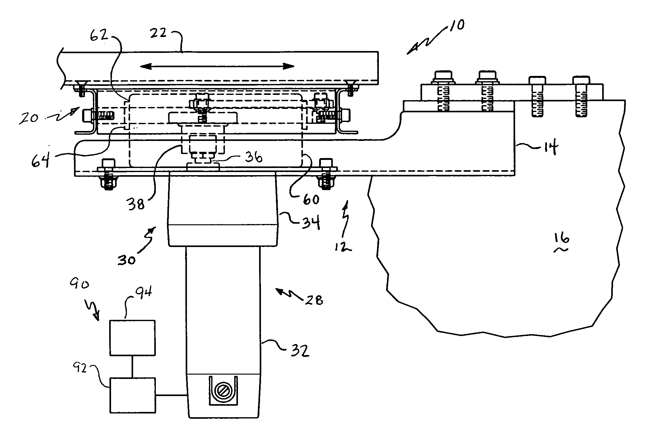
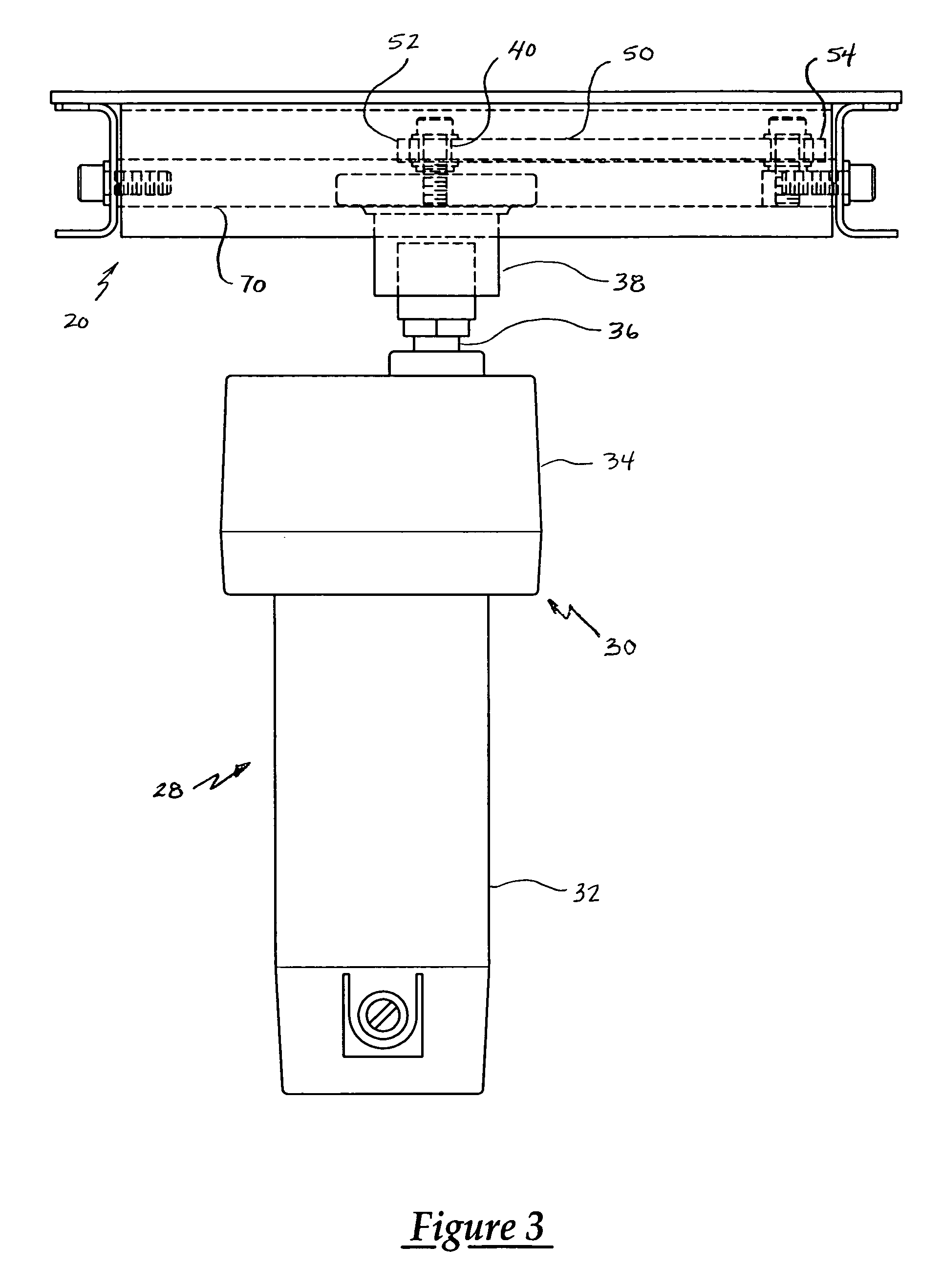
[0023] One embodiment of the shaker conveyor assembly of the present invention is generally indicated at 10 in FIGS. 1 through 3, where like numerals are used to designate like structure throughout the drawings. The shaker conveyor assembly 10 may be employed in any number of applications and neither the preceding discussion nor the description of the invention that follows should be interpreted as limiting the present use of the invention.

[0024] Referring now to FIG. 1, the conveyor assembly 10 of the present invention includes a stationary base, generally indicated at 12. It should be appreciated by those having ordinary skill in the art that due to the wide variety of possible applications and operating environments that the present invention may be incorporated into any type of mounting that rigidly supports the conveyor assembly 10. For example, the stationary base 12 may be a mounting bracket 14 (as illustrated in FIG. 1) or the like that further secures the conveyor assembl...


PUM


Abstract

A shaker conveyor assembly for moving objects includes a conveying element adapted for movement in first and second directions in repeated rectilinear fashion so as to convey items placed on the conveying element in one of the directions. The assembly includes an electric drive assembly having an output, a control assembly, and at least one sensor adapted to sense movement of the output. The control assembly provides a first level of electrical power to the electric drive assembly during a first portion of reciprocal movement and a second level of power to the electric drive assembly during a second portion of reciprocal movement. In addition, the control assembly provides selective control over the duration of the first and second portions of the reciprocal movement thereby controlling the speed of each of the directions of reciprocal movement of the conveying element.

Description

CROSS-REFERENCE TO RELATED APPLICATION(S) [0001] This application claims the benefit of U.S. Provisional Patent Application Ser. No. 60 / 701,643 entitled, “Shaker Conveyor Assembly Having An Electronically Controllable Stroke Speed,” filed on Jul. 22, 2005.BACKGROUND OF THE INVENTION [0002] 1. Field of the Invention [0003] The present invention is directed toward beltless conveyors and, more specifically, to a shaker conveyor having an electronically controllable stroke speed. [0004] 2. Description of the Related Art [0005] Conveyors are well known material handling devices that have application in a wide variety of environments for transporting objects from one place to another. For example, one type of conveyor employs a belt formed into an endless loop which is entrained about at least a pair of rollers spaced apart from one another and usually located at the opposed marginal ends of the conveyor. The rollers have sprockets at either end thereof. The spaced rollers are interconnec...

Claims


Application Information

Patent Timeline
Patent Type & Authority Applications(United States)
IPC IPC(8): B65G25/00
CPCB65G27/32B65G27/12
Inventor KWASNIEWICZ, RONALD W.
Owner MAGNETIC PRODS
Why Eureka
Try Eureka