Light Emitting Diode Package and Light Guide Pipe and Backlight Module and Liquid Crystal Display Device Using the Same

a technology of light guide pipe and diode package, which is applied in the direction of lighting support devices, lighting and heating apparatus, instruments, etc., can solve the problems of easy pollution of the environment by lamps, difficult recycling of cold and hot cathode fluorescent lamps after, and poisonous substances in cold and hot cathode fluorescent lamps

Inactive Publication Date: 2007-01-25
INNOLUX CORP
View PDF9 Cites 30 Cited by
  • Summary
  • Abstract
  • Description
  • Claims
  • Application Information

AI Technical Summary

Problems solved by technology

However, cold and hot cathode fluorescent lamps include poisonous substances, such as mercury.
It is not easy to recycle cold and hot cathode fluorescent lamps after long-time uses as the fluorescent lamps pollute the environment easily if not properly recycled.
Furthermore, with the current upsurge in environmental protection consciousness and tendency to recycle all electronic products, backlight modules with fluorescent lamps are recognized as environment unfriendly and, therefore, applicability of the conventional fluorescent backlight modules and liquid crystal display devices using the same is lowered greatly.

Method used


Image

  • Light Emitting Diode Package and Light Guide Pipe and Backlight Module and Liquid Crystal Display Device Using the Same
  • Light Emitting Diode Package and Light Guide Pipe and Backlight Module and Liquid Crystal Display Device Using the Same
  • Light Emitting Diode Package and Light Guide Pipe and Backlight Module and Liquid Crystal Display Device Using the Same

Examples


first embodiment

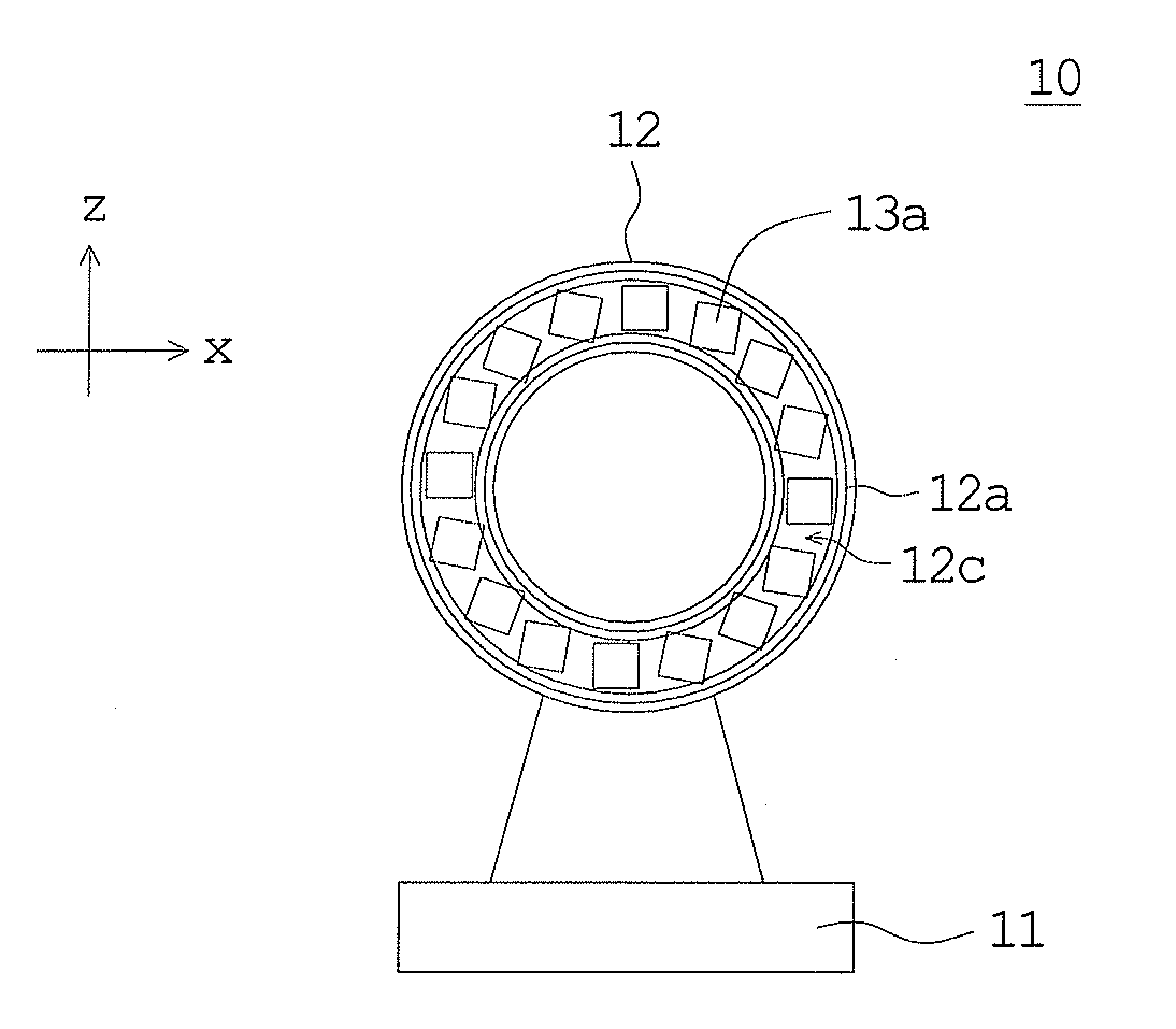
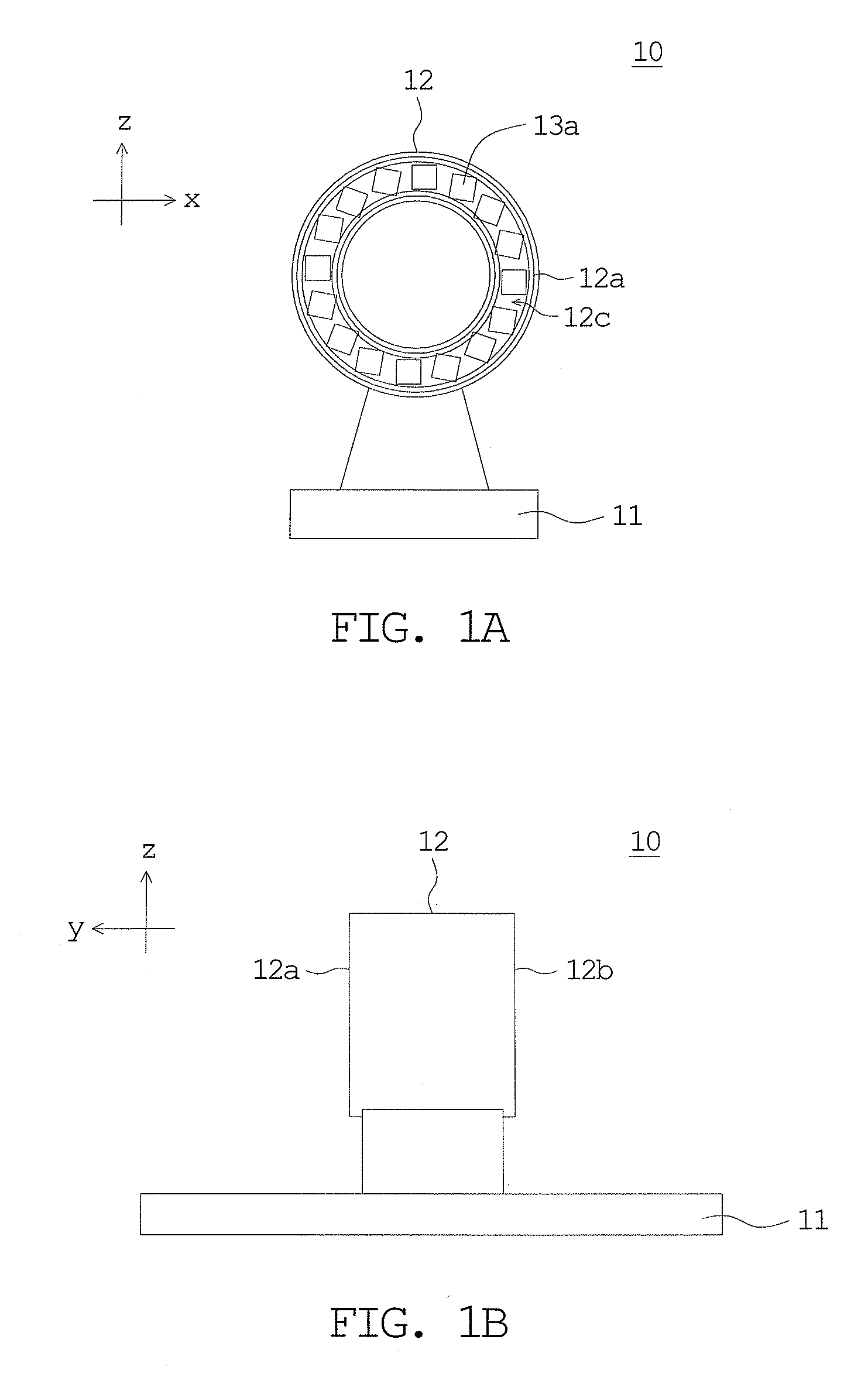
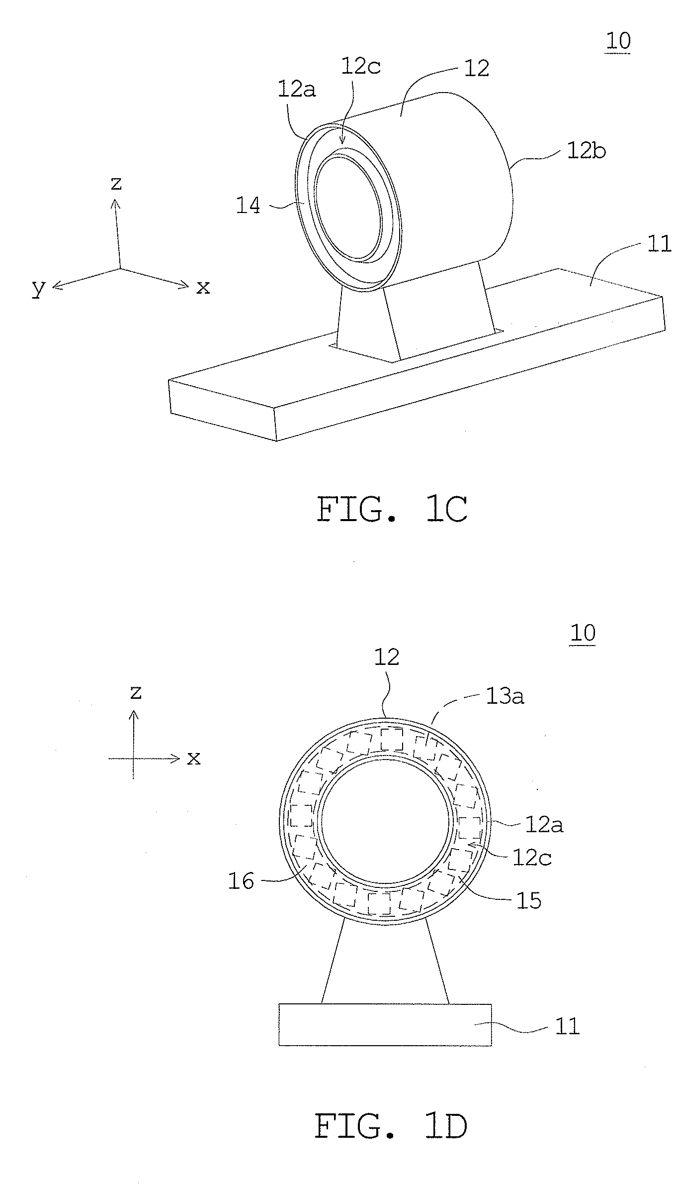
[0038]FIG. 1A is a front view of a light emitting diode package according to a first embodiment of the invention. FIG. 1B is a side view of the light emitting diode package in FIG. 1A. FIG. 1C is a three-dimensional view of a base and a body of the light emitting diode package in FIG. 1A. FIG. 1D is a front view of the light emitting diode package in FIG. 1A further including fluorescent powder and gel. FIG. 1E is a back view of the light emitting diode package in FIG. 1A further including the fluorescent powder and the gel.

[0039] As shown in FIGS. 1A˜1B, a light emitting diode package 10 includes a base 11, a body 12 and several first light emitting diode chips 13a. The body 12 is disposed on the base 11 and has a first end surface 12a. A first peripheral recess 12c is formed on the first end surface 12a. The first light emitting diode chips 13a are disposed on a bottom of the first peripheral recess 12c for providing the light emitting diode package 10 with single-direction sidel...

second embodiment

[0044]FIG. 2A is a three-dimensional view of a light guide pipe according to a second embodiment of the invention. FIG. 2B is a cross-sectional view of the light guide pipe in FIG. 2A viewed along +x direction with yz plane as a cross-sectional plane. FIG. 2C is a magnified cross-sectional view of the light guide pipe in FIG. 2A viewed along +y direction with xz plane as a cross-sectional plane. As shown in FIGS. 2A˜2C, the light guide pipe 20a is for receiving light emitted by a light source from one end of the light guide pipe 20a and for scattering, by refraction, the received light. The light guide pipe 20a includes a column 21 and several prism structures 22a. The column 21 has an external circumferential surface 21a and an internal reflection surface 21b. The internal reflection 21b is arranged for reflecting light received by the light guide pipe 20a. The prism structures 22a can be disposed between the external circumferential surface 21a and the internal reflection surface ...

third embodiment

[0050] In FIG. 3, a cross-sectional view of a light guide pipe according to a third embodiment of the invention is illustrated. The difference between a light guide pipe 20b of the present embodiment and the light guide pipe 20a of the second embodiment lies in prism structures 22b. The same components use the same reference numbers and are not described again.

[0051] As shown in FIG. 3, although the prism structures 22b of the present embodiment and the prism structures 22a of the second embodiment all includes pattern dots, the pattern dots of the present embodiment are concave dots or cavities, rather than protrusions. A manufacturing method of the light guide pipe 20b in the present embodiment is substantially the same as that of the light guide pipe 20a in the second embodiment and is not described again. Besides, the distribution and manufacturing method of the prism structures 22b in the present embodiment are substantially the same as those in the second embodiment and are n...


PUM


Abstract

A light emitting diode (LED) package includes a base, a body and several LED chips. The body having an end surface is disposed on the base. A peripheral recess is formed in the end surface. The LED chips are disposed on a bottom of the peripheral recess for providing sidelight of the LED package. The LED package is connectable to a light guide pipe including a column having an external circumferential surface and an internal reflection surface, and a plurality of prism structures disposed between or on at least one of the external circumferential surface and the internal reflection surface for scattering light received by the light guide pipe from the LED package.

Description

[0001] This application claims the benefit of Taiwan application Ser. No. 94124414, filed Jul. 19, 2005, the entirety of which is incorporated herein by reference. BACKGROUND [0002] 1. Technical Field [0003] The invention relates in general to a backlight module and a liquid crystal display device, and more particularly, to a light emitting diode package, a light guide pipe, and a backlight module and a liquid crystal display device using the same. [0004] 2. Related Art [0005] It has been known in the art that a liquid crystal display panel in a liquid crystal display device is not self-luminous, the liquid crystal display panel needs a backlight module to provide backlight in order to display images. A cold cathode fluorescent lamp or a hot cathode fluorescent lamp is generally used in a conventional backlight module as a light source. [0006] However, cold and hot cathode fluorescent lamps include poisonous substances, such as mercury. It is not easy to recycle cold and hot cathode...

Claims


Application Information

Patent Timeline
Patent Type & Authority Applications(United States)
IPC IPC(8): H01L33/00F21K99/00
CPCF21K9/00G02B6/0001G02B6/0043G02F1/133603G02B6/0073G02B6/0096G02B6/4298G02B6/0061F21K9/68Y10S362/80
Inventor HUNG, CHEN-PIN
Owner INNOLUX CORP
Why Eureka
Try Eureka