Color picture tube

a color picture and tube technology, applied in the field of color picture tubes, can solve the problems of increasing the weight of the panel b, reducing the brightness, and reducing the image characteristics, and achieve the effect of suppressing the degradation of color purity caused by doming, enhancing the visibility and the formability of the shadow mask

Inactive Publication Date: 2007-01-25
MATSUSHITA TOSHIBA PICTURE DISPLAY CO LTD
View PDF5 Cites 0 Cited by
  • Summary
  • Abstract
  • Description
  • Claims
  • Application Information

AI Technical Summary

Benefits of technology

[0020] The present invention has been achieved in view of the above conventional problems, and its object is to provide a color picture tu...

Problems solved by technology

In the color picture tube, increased thickness of the center of the useful portion 1 of the panel 3 causes not only the degradation in image characteristics such as the decrease in brightness, but also the increase in weight of the panel 3 and the like, which is disadvantageous in terms of cost.
On the other hand, decreased thickness can enhance the brightness and the like, which is advantageous for image characteristics; however, it degrades implosion-protection characteristics and increases the leakage of an X-ray.
Consequently, when the q value of the interval between the inner surface of the useful portion 1 of the panel 3 and the shadow mask 7 falls outside an allowable range, electron beams do not land on desired phosphor layers and cause so-called mislanding, which degrades color purity.
In the local doming, the amount of a landing positional shift is large, so that the degradation in color purity is large.
Furthermore, the iron-nickel alloy has large elasticity after annealing, so that it is difficult to form a curved surface from such an alloy by forming and to obtain a desired curved surface.
Particularly, in a color picture tube in whic...

Method used


Image

  • Color picture tube
  • Color picture tube
  • Color picture tube

Examples


embodiment 1

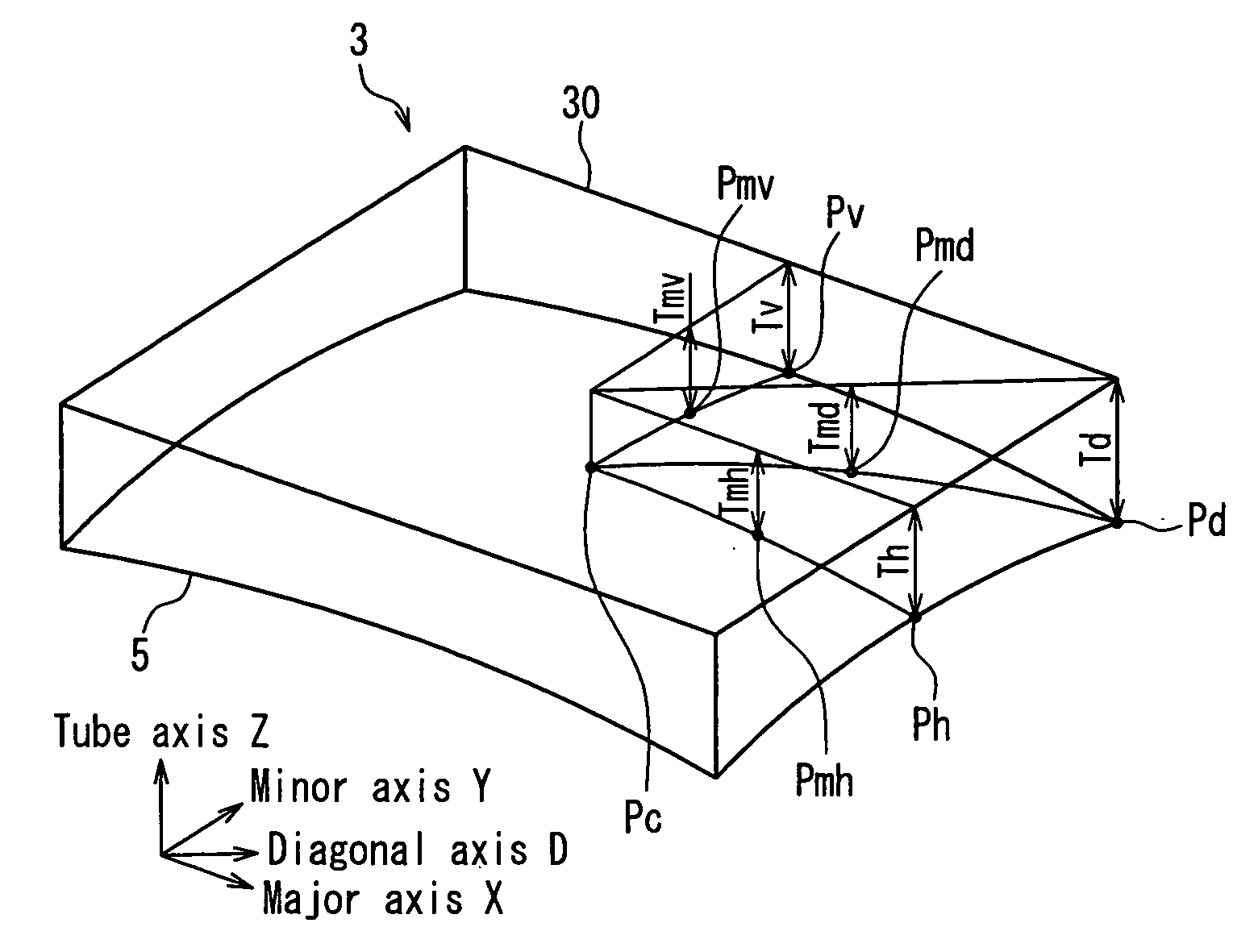
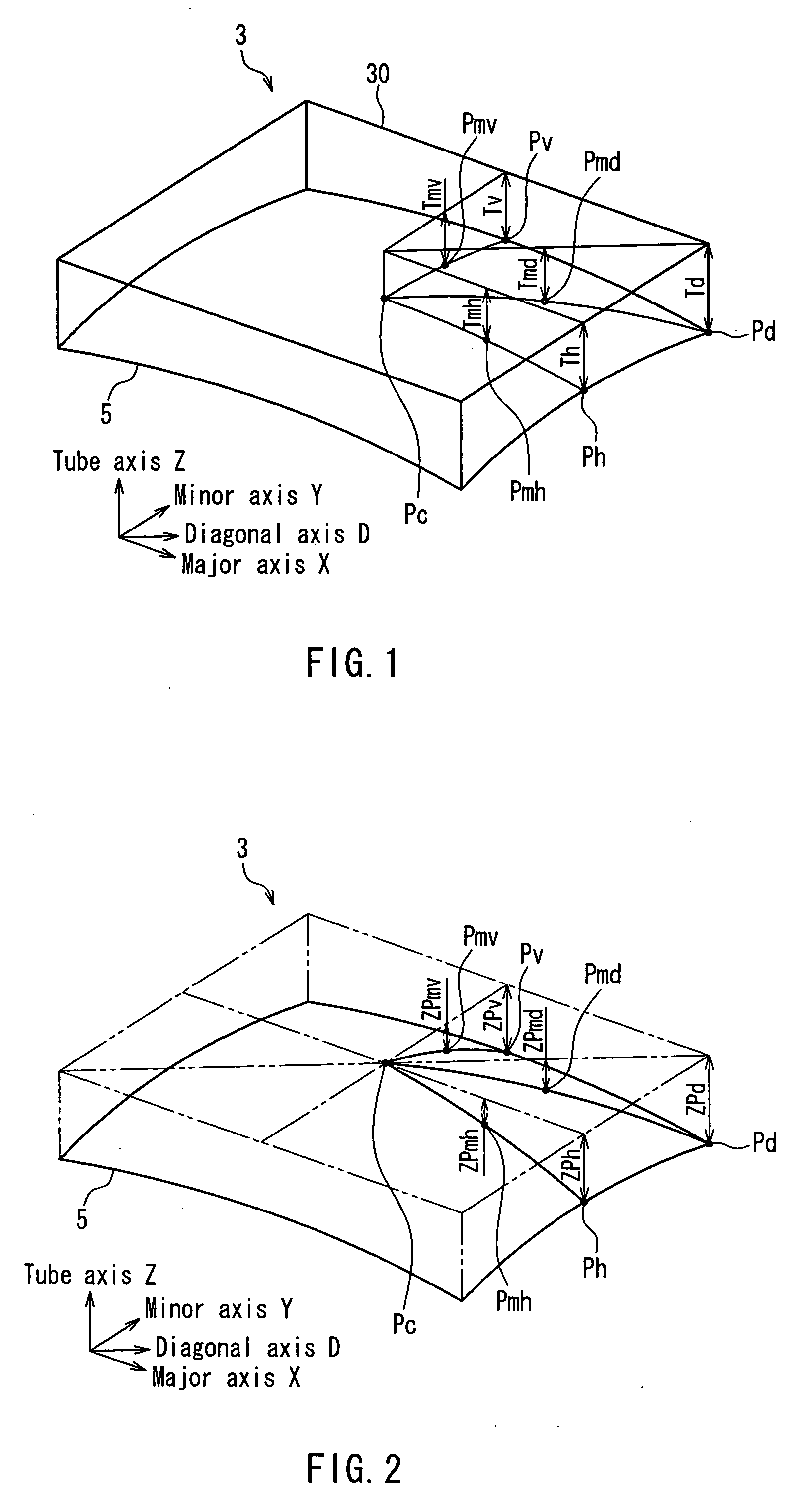
[0037]FIG. 7 is a cross-sectional view of a color picture tube according to one embodiment of the present invention. The color picture tube includes a vacuum envelope 9 composed of a panel 3 in which a skirt portion 2 is provided on the periphery of a useful portion 1 in a substantially rectangular shape, and a funnel 4 in a funnel shape connected to the skirt portion 2. On an inner surface of the useful portion 1 of the panel 3, a phosphor screen 5 is formed in a substantially rectangular shape, which is composed of black non-light-emitting material layers and three-color phosphor layers in a stripe or dot shape provided in regions where the black non-light-emitting material layers are not formed. A shadow mask 7, having a perforated region in a substantially rectangular shape in which a number of electron beam passage apertures are arranged in vertical and horizontal directions, is placed so as to be opposed to the phosphor screen 5. The shadow mask 7 is held on a mask frame 8 in ...

embodiment 2

[0060] In the example described in Embodiment 1, the relationship between the thickness ratio Tmv / Tv and the amount of a landing positional shift of electron beams (“beam movement amount”) was obtained under the condition of setting the thickness Tv of the panel 3 at the minor axis end Pv of the phosphor screen 5 to be constant, and changing the thickness Tmv of the panel 3 at the minor axis intermediate point Pmv. In the same way as in FIG. 4, the measurement was performed with respect to two display patterns: the case where a white display was performed only in the region 20 including the major axis intermediate point Pmh and a black display was performed in the other regions (“major axis intermediate”) as shown in FIG. 8, and the case where a white display was performed only in the region 21 including the diagonal axis intermediate point Pmd and a black display was performed in the other regions (“diagonal axis intermediate”) as shown in FIG. 9. FIG. 6 shows the results.

[0061] I...


PUM


Abstract

A radius of curvature of an arc passing through three points on an outer surface of a panel, which respectively correspond to a pair of diagonal axis ends on one diagonal axis of a phosphor screen and a center of the phosphor screen, is 10,000 mm or more. A shadow mask is made of an aluminum killed material. Assuming that a thickness of the panel is Td at the diagonal axis end of the phosphor screen, Tmd at an intermediate point between the diagonal axis end and the center, Th at a major axis end of the phosphor screen, and Tmh at an intermediate point between the major axis end and the center, 0.5 ≦Tmd/Td≦0.62, and 0.65≦Tmh/Th≦0.80 are satisfied. Because of this, an inexpensive color picture tube can be provided, in which the visibility is excellent, the degradation in color purity caused by doming is suppressed, and the formability of the shadow mask is enhanced.

Description

BACKGROUND OF THE INVENTION [0001] 1. Field of the Invention [0002] The present invention relates to a color picture tube. [0003] 2. Description of Related Art [0004] In general, as shown in FIG. 7, a color picture tube includes a vacuum envelope 9 composed of a panel 3 in which a skirt portion 2 is provided on the periphery of a substantially rectangular useful portion 1, and a funnel 4 in a funnel shape connected to the skirt portion 2. On an inner surface of the useful portion 1 of the panel 3, a phosphor screen 5 is formed in a substantially rectangular shape, which is composed of black non-light-emitting material layers and three-color phosphor layers in a stripe or dot shape provided in regions where the black non-light-emitting material layers are not formed. A shadow mask 7 is placed so as to be opposed to the phosphor screen 5, which has a perforated region in a substantially rectangular shape where a number of electron beam passage apertures are arranged in vertical and ho...

Claims


Application Information

Patent Timeline
IPC IPC(8): H01J29/86H01J29/92
CPCH01J2229/862H01J29/861
Inventor KOJIMA, TADAHIROMURAI, TAKASHINAKAYAMA, TAKESHI
Owner MATSUSHITA TOSHIBA PICTURE DISPLAY CO LTD
Why Eureka
Try Eureka