Image forming apparatus utilizing a piezoelectric-transformer high-voltage power supply and method for controlling the same

a piezoelectric transformer and high-voltage power supply technology, applied in the field of image forming apparatus, can solve the problems of inability to respond to the input signal, inability to transfer, and long response time, and achieve the effect of stable output and rising tim

a piezoelectric transformer and high-voltage power supply technology, applied in the field of image forming apparatus, can solve the problems of inability to respond to the input signal, inability to transfer, and long response time, and achieve the effect of stable output and rising tim

US20070018589A1Active Publication Date: 2007-01-25CANON KK

Image

  • Image forming apparatus utilizing a piezoelectric-transformer high-voltage power supply and method for controlling the same
  • Image forming apparatus utilizing a piezoelectric-transformer high-voltage power supply and method for controlling the same
  • Image forming apparatus utilizing a piezoelectric-transformer high-voltage power supply and method for controlling the same

Examples


first exemplary embodiment

Exemplary Imaging Apparatus

[0027]FIG. 3 illustrates the structure of an exemplary color laser printer 401 serving as an exemplary image-forming apparatus (i.e., platform) according to the first embodiment. The laser printer 401 includes a deck 402 configured to store sheets of recording paper (hereinafter, referred to as recording papers) 32, each serving as a transfer material; a deck-paper detecting sensor 403 configured to detect presence of the recording paper 32 in the deck 402; a pickup roller 404 configured to deliver out the recording paper 32 from the deck 402; a deck-paper feeding roller 405 configured to transport the recording paper 32 delivered out by the pickup roller 404; and a retard roller 406 configured to pair off with the deck-paper feeding roller 405 and prevent the recording papers 32 from being transported in an overlapped manner. In addition, at the downstream of the deck-paper feeding roller 405, a registration roller pair 407 and a registration roller fro...

second exemplary embodiment

[0057] A second embodiment of the present invention will now be described. Description of like parts as those described in the first embodiment is omitted.

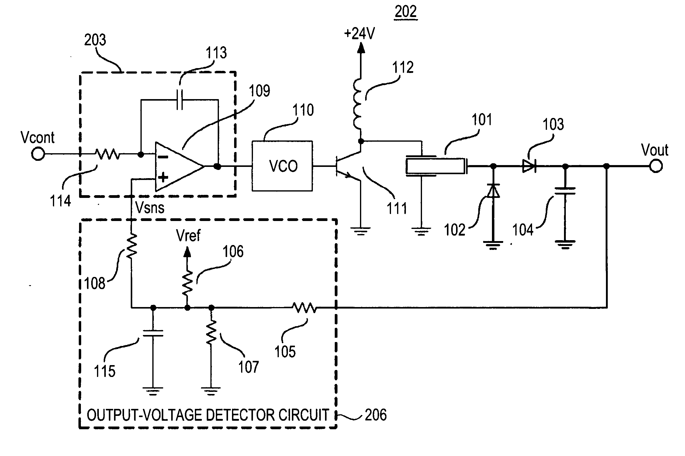
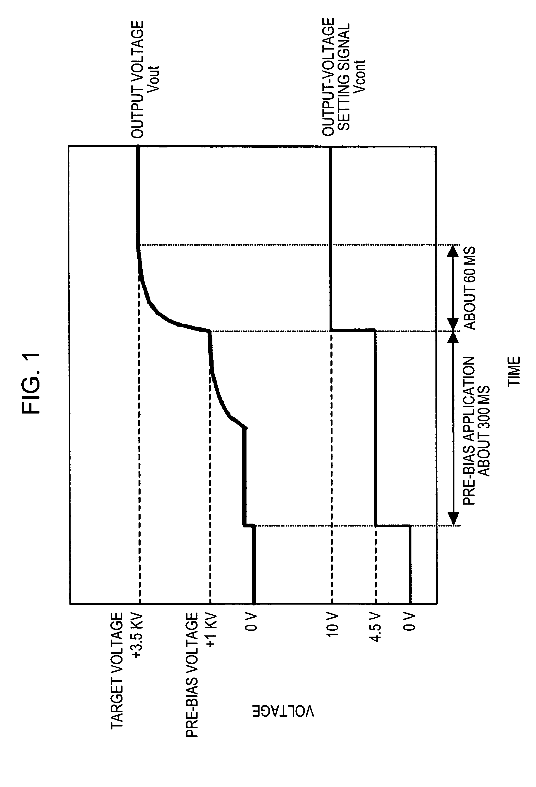
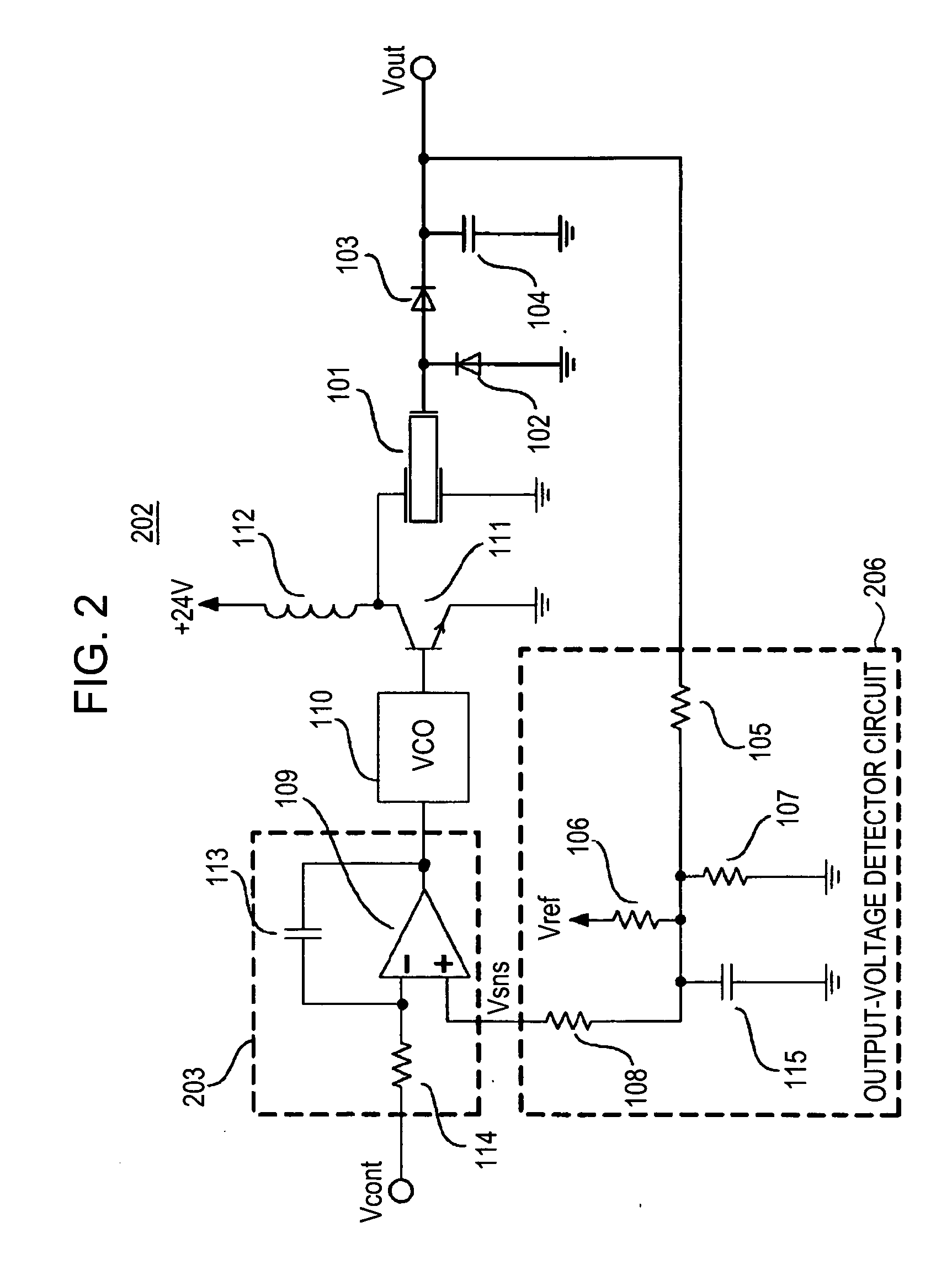
[0058] The second embodiment has a feature that, with respect to controlling an output of the piezoelectric-transformer high-voltage power supply 202, as shown in FIG. 6, the output is controlled so as to increase up to the final target voltage in a stepwise manner after having a pre-bias voltage applied thereon. In the present embodiment, by changing the voltage-controlling target value in three stages up to the final target voltage after application of the pre-bias voltage, the output voltage increases in a stepwise manner so as to attain the final target voltage.

[0059] In the circuit diagram shown in FIG. 2, with the integral circuit configured by the resistor 114 and the capacitor 113, an output-voltage setting voltage V in each stage input into the operational amplifier 109 of a voltage-comparing section (the comparator cir...


PUM


Abstract

A piezoelectric-transformer high-voltage power supply in combination with an image-forming apparatus including a latent-image forming section configured to form an electrostatic latent image on an image carrier, a developing section configured to form a toner image on the electrostatic latent image, and a transfer section configured to transfer the toner image onto a transfer material includes a piezoelectric transformer; a piezoelectric-transformer drive circuit; an output-voltage setting-signal output circuit configured to output an output-voltage setting-signal; an output-voltage detector circuit, and a drive control circuit configured to output a control signal on the basis of a signal from the output-voltage detector circuit and the output-voltage setting-signal, for controlling the piezoelectric-transformer drive circuit. The output-voltage setting-signal output circuit outputs an output-voltage setting-signal corresponding to a voltage lower than a target voltage and, then, another output-voltage setting-signal corresponding to the target voltage.

Description

BACKGROUND OF THE INVENTION [0001] 1. Field of the Invention [0002] The present invention relates to an imaging apparatus which utilizes a piezoelectric-transformer high-voltage power supply, and a method for controlling the same. [0003] 2. Description of the Related Art [0004] In an image-forming apparatus of an electrophotographic process type, reduction in the size and weight of a high-voltage power supply adapted for providing a direct-current bias voltage and the like involved in forming an image by a transfer section leads to reduction in the size and weight of the image-forming apparatus. Hence, in place of an electromagnetic transformer of a winding type, making use of a thin, light, and high-power piezoelectric transformer has been studied so as to serve as a transformer of a high-voltage power supply. [0005] Use of a piezoelectric-transformer composed of a ceramic material enables the high-voltage power supply to generate a high voltage with a higher efficiency than that o...

Claims


Application Information

Patent Timeline
25 Jan 2007
Publication
US20070018589A1
IPC
F02P3/12
CPC
H01L41/044; G03G15/80; H10N30/804
Inventors
SAITO, TOHRU; SUZUKI, MASAHIRO