
Apparatus and method for local broadcasting in the twenty-six megahertz short wave band

a short wave band and electromagnetic signal technology, applied in the field of radio frequency electromagnetic signal (rf) broadcasting, can solve the problems of high cost and poor quality of analog transmission, and achieve the effect of suppressing sky wave emission

Inactive Publication Date: 2007-01-25
TCI INT
View PDF8 Cites 13 Cited by
  • Summary
  • Abstract
  • Description
  • Claims
  • Application Information

AI Technical Summary

Benefits of technology

"The present invention provides an apparatus for a short wave broadcast antenna that suppresses sky wave emission while providing gain for low-elevation signals, making it suitable for line-of-sight broadcasting service from ground-mounted transmitting towers. The antenna system includes a first radiator and a signal directing apparatus that directs energy from the first radiator in a way that supports ionospheric reflective / refractive propagation and reinforces line-of-sight propagation. The antenna system can also include a reflector positioned further from a mean terrain surface than the first radiator and a second radiator that interferes with the first radiator in a sky wave direction and constructively interferes with it in a terrestrial wave direction. The method for broadcasting short wave radio frequency electromagnetic signals involves emitting a vertically-polarized RF signal from a mounting point on a broadcast tower and directing it to suppress sky wave propagation and reinforce line-of-sight propagation. The invention has applications in various forms and can be used in different ways."

Problems solved by technology

Analog transmissions are often of poor quality because of fading and interference from both human-made and natural sources.
In the present era, a broadcaster who desires to establish a new service has had to purchase an allocation from another broadcaster, often at enormous expense.

Method used


Image

  • Apparatus and method for local broadcasting in the twenty-six megahertz short wave band
  • Apparatus and method for local broadcasting in the twenty-six megahertz short wave band
  • Apparatus and method for local broadcasting in the twenty-six megahertz short wave band

Examples


Embodiment Construction

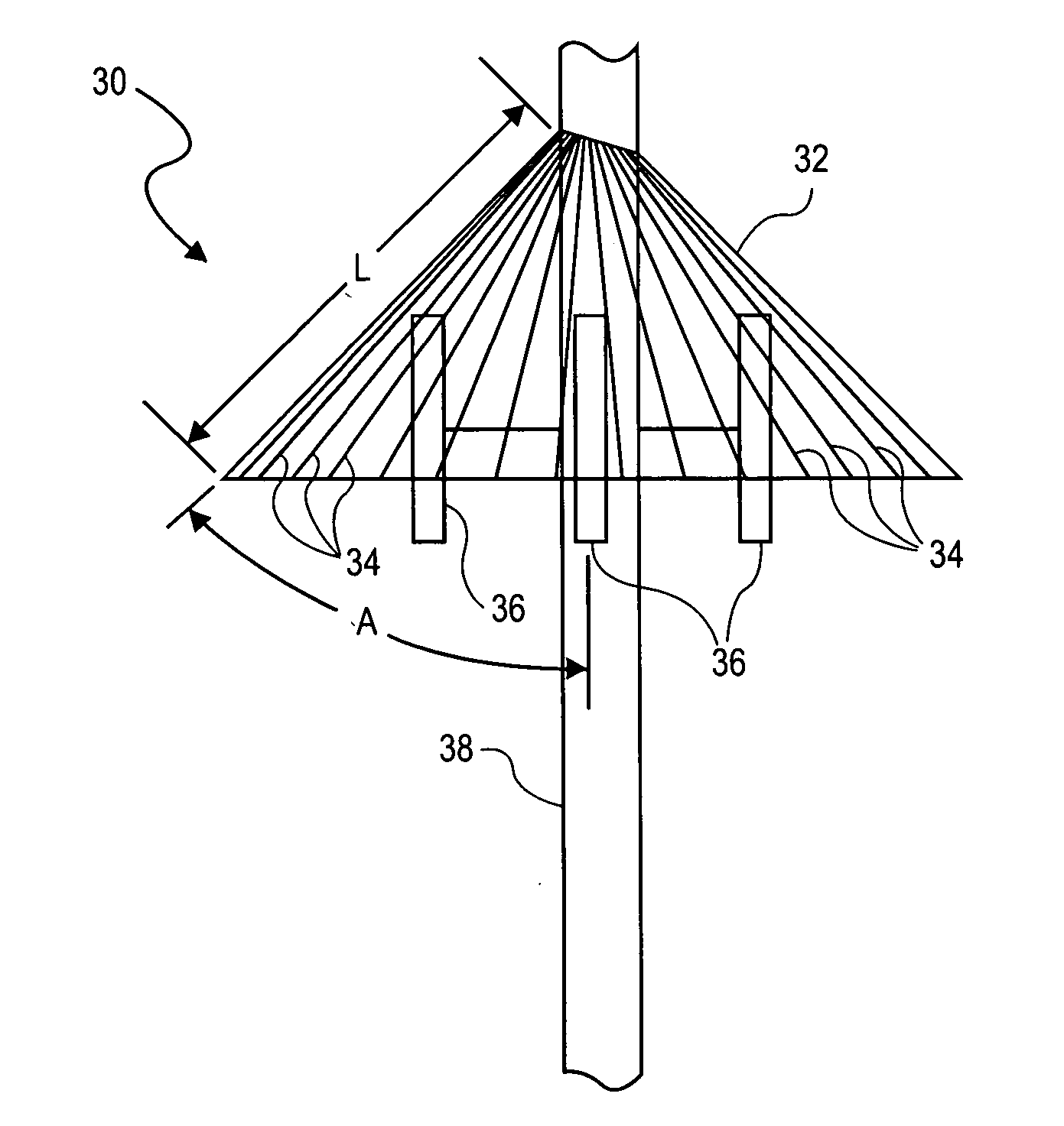
[0032] The invention will now be described with reference to the drawing figures, in which like reference numerals refer to like parts throughout. The present invention provides an apparatus and method that in some embodiments provides an antenna that suppresses sky wave emission while broadcasting short wave signals by line of sight.

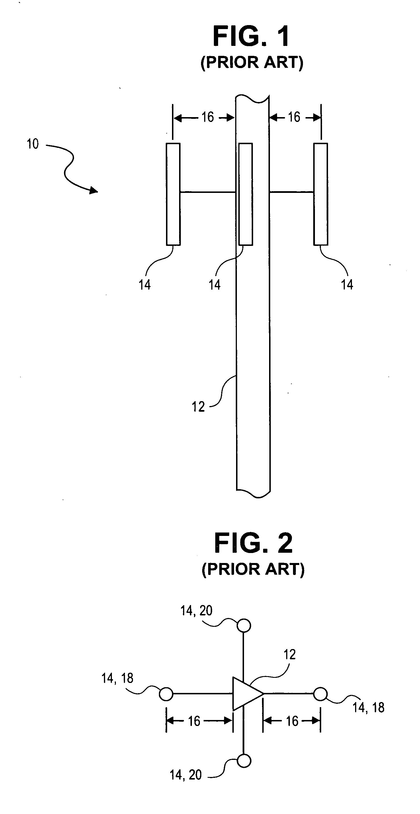
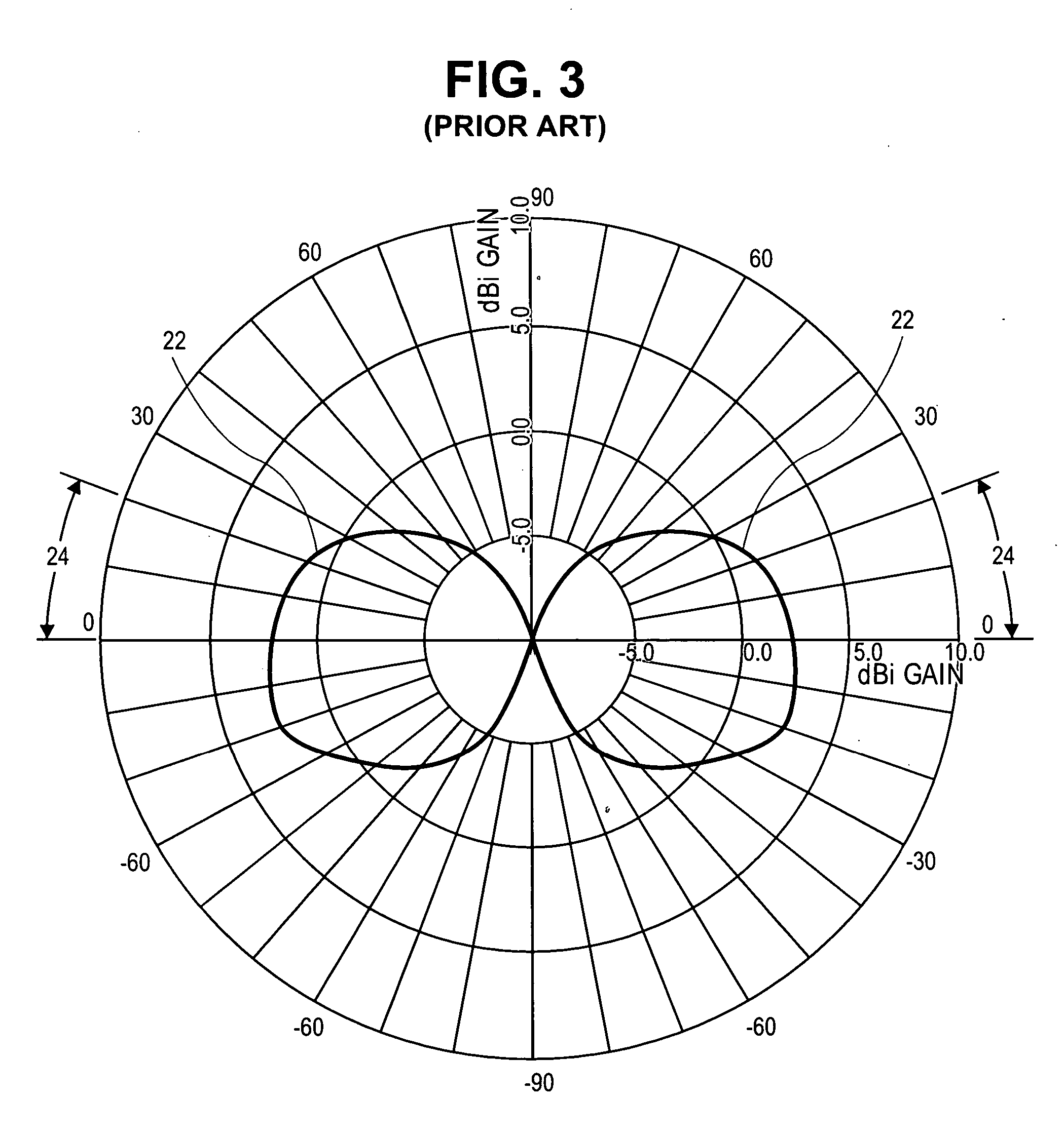
[0033]FIG. 1 shows a typical structural arrangement for an antenna 10 and mast section 12, wherein the antenna 10 is intended to broadcast substantially uniformly in all azimuth directions. In the 26 MHz operating band, the size of the radiators in an antenna system is approximately four times as large in every dimension as those in a comparable FM band (VHF) antenna system. While generic radiating elements (which could be dipoles, reflector-backed panel radiators, or the like) are shown in the majority of the figures herein, it is to be understood that any type of radiator suitable for positioning with respect to a tower and for operating at a power l...


PUM


Abstract

A short wave omnidirectional antenna for the 26 Megahertz band provides line-of-sight broadcasting at comparatively low power to serve local communities while suppressing sky wave propagation. Sky wave suppression is achieved by a critically configured reflector above the radiator or by a co-located second active or parasitic radiator spaced to achieve sufficient beam tilt to create a null at critical angles, generally from the horizon to thirty degrees above. This arrangement allows local broadcasts to be originated at numerous sites despite the narrow extent of the band (330 kHz) and the narrow (10 kHz) channel width. Among other possible applications, the antenna supports transmission using the Digital Radio Mondiale® (DRM®) system for COFDM. COFDM technology can suppress ghosting and most noise, while low emission angle of the antenna and low intended transmitter power largely prevent interference between broadcasts at moderate distances.

Description

CLAIM OF PRIORITY [0001] This application claims priority to U.S. Provisional Application entitled, “Description of Antenna for Transmitting Short Wave Signals in the 26 MHz Band”, filed Jul. 22, 2005, having Ser. No. 60 / 701,511, which is hereby incorporated by reference in its entirety.FIELD OF THE INVENTION [0002] The present invention relates generally to radio frequency electromagnetic signal (RF) broadcasting. More particularly, the present invention relates to techniques for broadcasting electromagnetic signals in the 26 MHz Short Wave band with sky wave suppression. BACKGROUND OF THE INVENTION [0003] There is a trend toward adoption of digital technology in radio and communications, especially for distribution and transmission. Digitization offers substantial advantages to national and international broadcasters in the short wave bands from 2 to 30 MHz. Analog transmissions are often of poor quality because of fading and interference from both human-made and natural sources. ...

Claims


Application Information

Patent Timeline
Patent Type & Authority Applications(United States)
IPC IPC(8): H04Q7/20
CPCH01Q1/246H01Q1/526H01Q3/2611H01Q15/168H01Q21/29H01Q19/13H01Q19/28H01Q21/10H01Q21/205H01Q19/12
Inventor CHENG, PO-SHINSINCLAIR, GORDON G.
Owner TCI INT
Learn More