

Serial data transmission method and system
- Summary
- Abstract
- Description
- Claims
- Application Information
AI Technical Summary
Benefits of technology
Problems solved by technology
Method used
Image

Examples
first embodiment
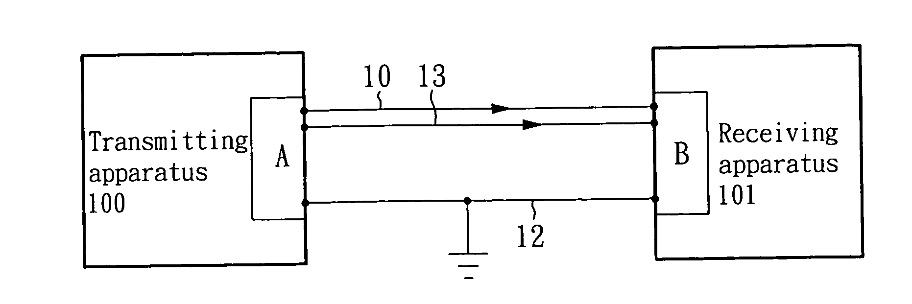
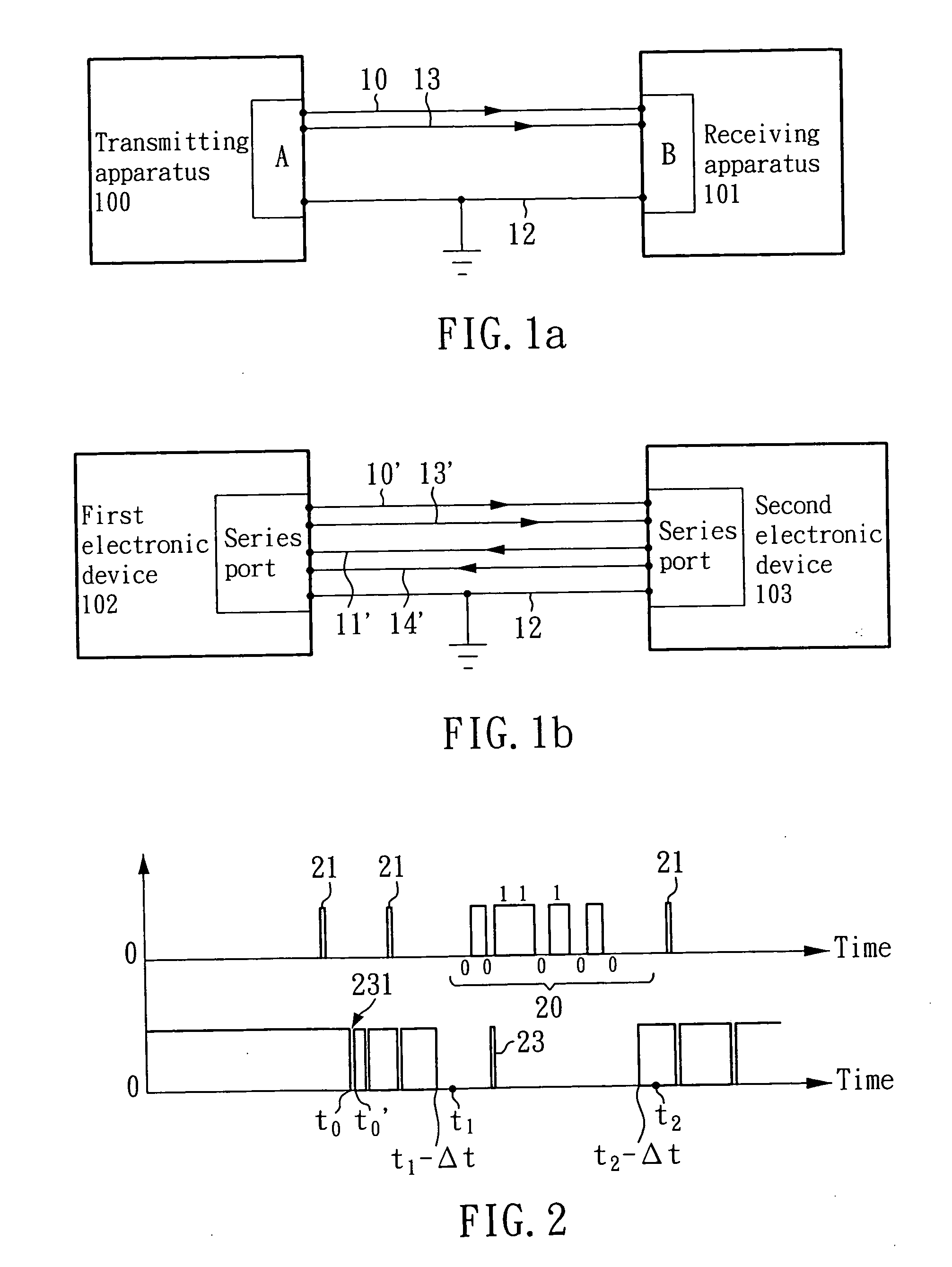
[0018]FIG. 1a is a schematic drawing showing a serial data transmission system according to the present invention. The system takes one way serial data transmission for example, particularly for a serious data transmission method in high signal-to-noise ration circumstances, such as in car or RS-232 of serious data transmission method in the laboratory. According to FIG. 1a, a serial data is transmitted from the transmitting connector A of the transmitting apparatus 100 to the receiving connector B of the receiving apparatus 101. The first transmission line 10 transmits the serial data, the second transmission line 13 transmits the control signal, and the ground line 12 provides the reference voltage zero.
second embodiment
[0019]FIG. 1b is a schematic drawing showing a serial data transmission system according to the present invention. This embodiment is a bi-directional transmission RS-232 of serious data transmission system. The first transmission line 10′ and the second transmission line 13′ are respectively transmitted the serial data and the control signal from the series port of the first electronic device 102 to the series port of the second electronic device 103. The third transmission line 11′ and the fourth transmission line 14′ are respectively transmitted the serial data and the control signal from the series port of the second electronic device 103 to the series port of the first electronic device 104.
[0020] All of above transmission lines can modify in the form of ports to connect two different electronic devices, such as a main sever for car, a guard device, a display device, a GPS system, etc., for providing the correct transmission between two electronic devices.
[0021] To simplify ex...
third embodiment
[0030]FIG. 4 shows the present invention. This third embodiment changes the control signal on the second transmission line 13 to be the status on the lower part in FIG. 4. The upper part in FIG. 4 shows the data transmitted through the first transmission line 10. The lower part in FIG. 4 shows the control signal on the second transmission line 13. According to this embodiment, the control signal is a binary control signal. The system sets the start signal for the first specific condition to start receiving data as “01101”, and the end signal for the second specific condition to end the receiving action as “10010”. Therefore, the receiving connector B will only receive the serial data 40 transmitted through the first transmission line 10 within the time period from the start time point t3 till the end time point t4. The aforesaid start signal and end signal can both be set as “01101”.
[0031] According to this embodiment, there are many noises 43 and 431 on the second transmission line...
PUM
 Abstract
Description
Claims
Application Information