
Method and apparatus for inspecting pneumatic tire during production

Inactive Publication Date: 2007-02-01
TOYO TIRE & RUBBER CO LTD
View PDF2 Cites 25 Cited by
  • Summary
  • Abstract
  • Description
  • Claims
  • Application Information

AI Technical Summary

Benefits of technology

[0011] The invention was made in the light of the views pointed out above and an object thereof is to provide a method and apparatus which can reduce largely the amount of defects that are generated in association with low uniformity and can also reduce time until the production is resumed by measuring and controlling the eccentric amount of beads after they have been set in place.
[0017] According to the invention, since the beads are inspected on the eccentric amounts thereof, which affect largely the uniformity of a completed tire, after they have been provided on the tire building drum, a defect can be detected in the midst of production. Due to this, the generation of defects is largely reduced in amount, thereby making it possible to reduce material costs. In addition, a failed location in the mechanical facility can be verified early, so as to enable the failure to be dealt with in a smooth fashion, thereby making it possible to reduce time during which the relevant mechanical part of the facility is out of operation.

Problems solved by technology

Namely, while laser sensors can be used as the distance sensors, in the event of laser sensors, when the bead wires are covered with rubber such as a carcass ply or a rim strip, a distance as far as the surface of the rubber is to be measured, and hence, it is hard to measure accurately an eccentric amount of the bead wire.
In the event that the carcass ply contains metallic cords, however, since it is hard to measure the distance to the bead wire even with the eddy current sensor, the eddy current sensors become effective in a case where the carcass ply is made of only non-conductive cords.

Method used


Image

  • Method and apparatus for inspecting pneumatic tire during production
  • Method and apparatus for inspecting pneumatic tire during production
  • Method and apparatus for inspecting pneumatic tire during production

Examples


Embodiment Construction

[0025] Hereinafter, an embodiment of the invention will be described by reference to the accompanying drawings.

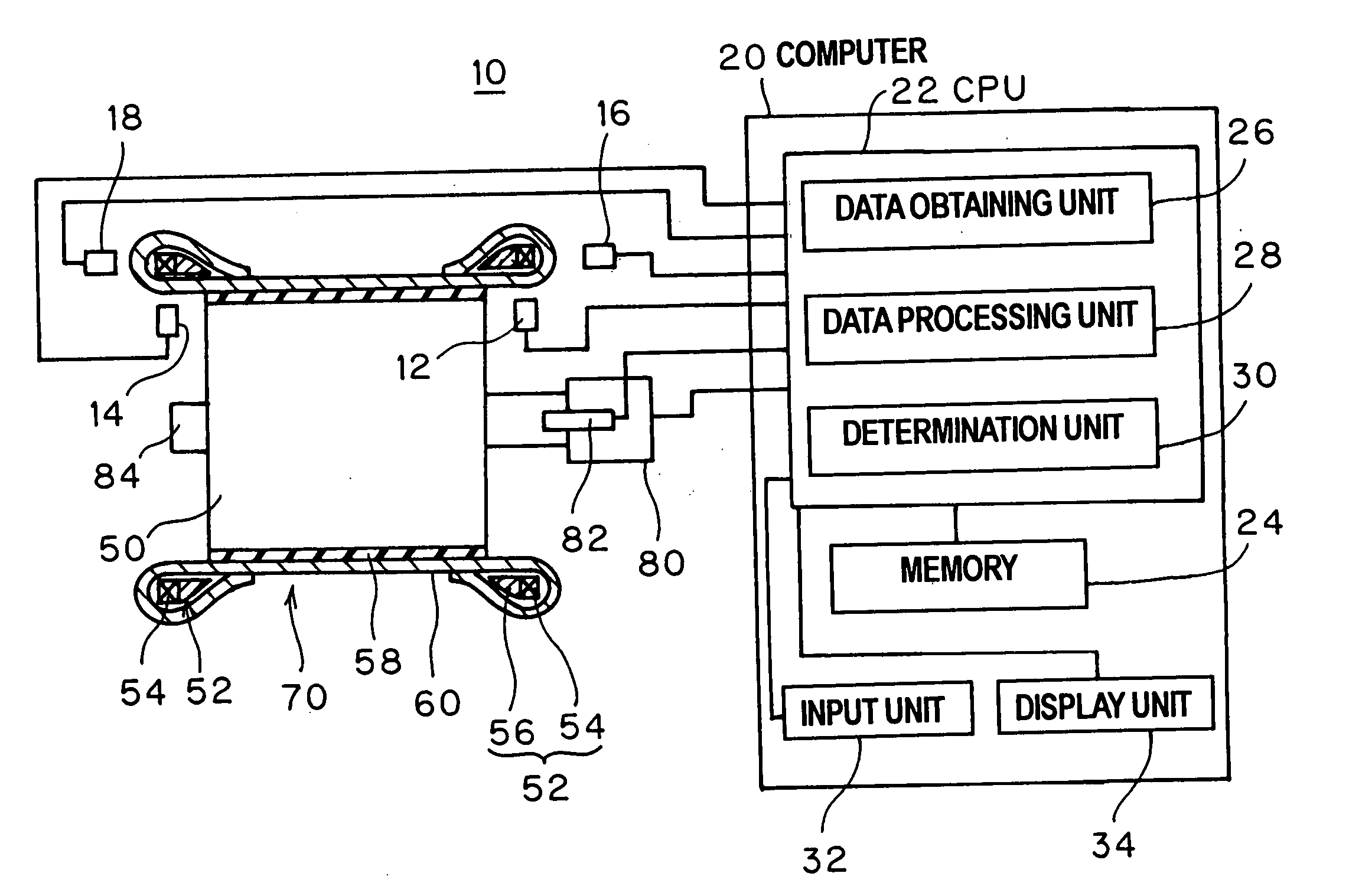
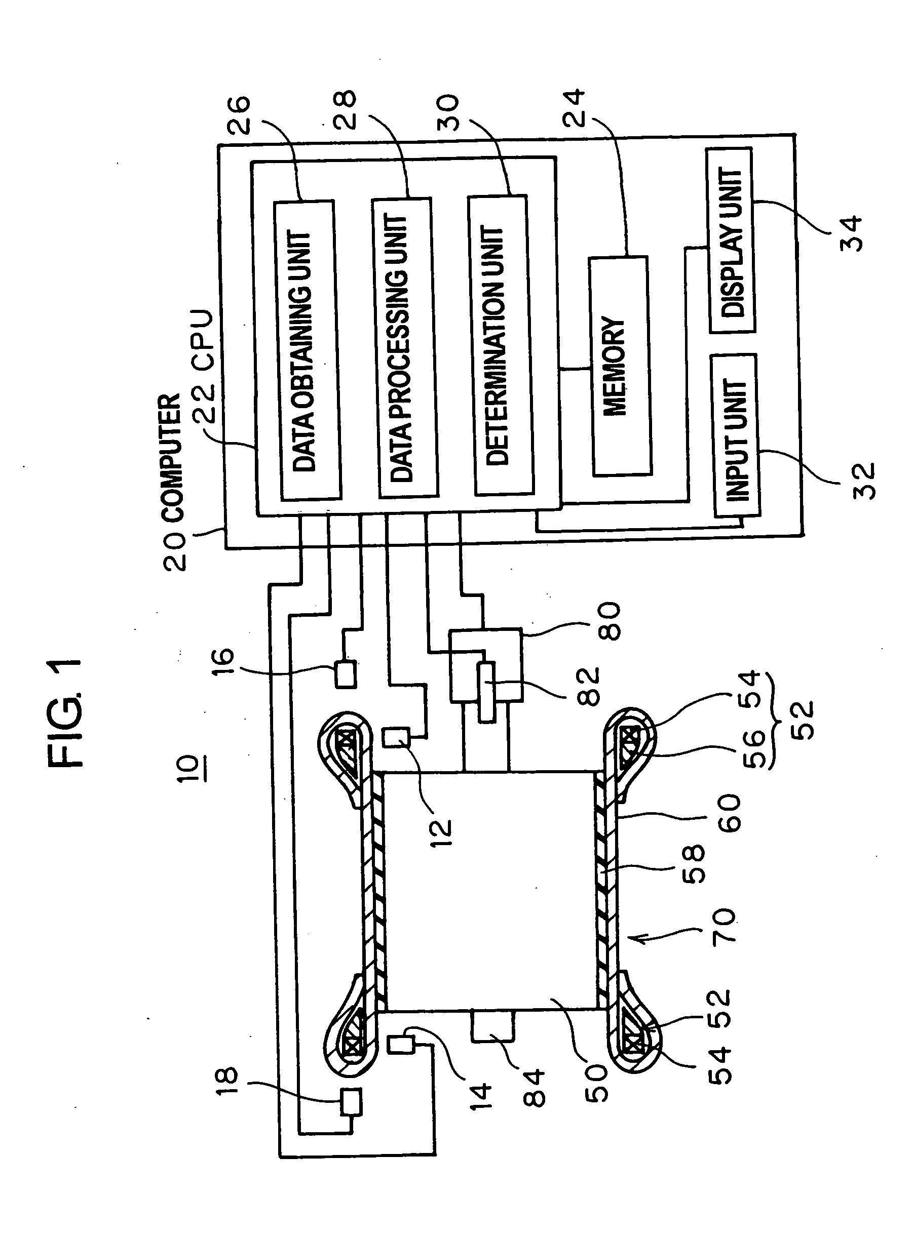
[0026]FIG. 1 is an exemplary diagram which shows the configuration of an inspection apparatus 10 according to the embodiment. This inspection apparatus 10 includes a pair of left and right, first and second distance sensors 12, 14 for detecting displacement amounts of beads 52, which are set on a tire building drum 50, in a radial direction thereof, a pair of left and right, third and fourth distance sensors 16, 18 for detecting displacement amounts of the beads 52 in an axial direction of the drum, and a computer 20.

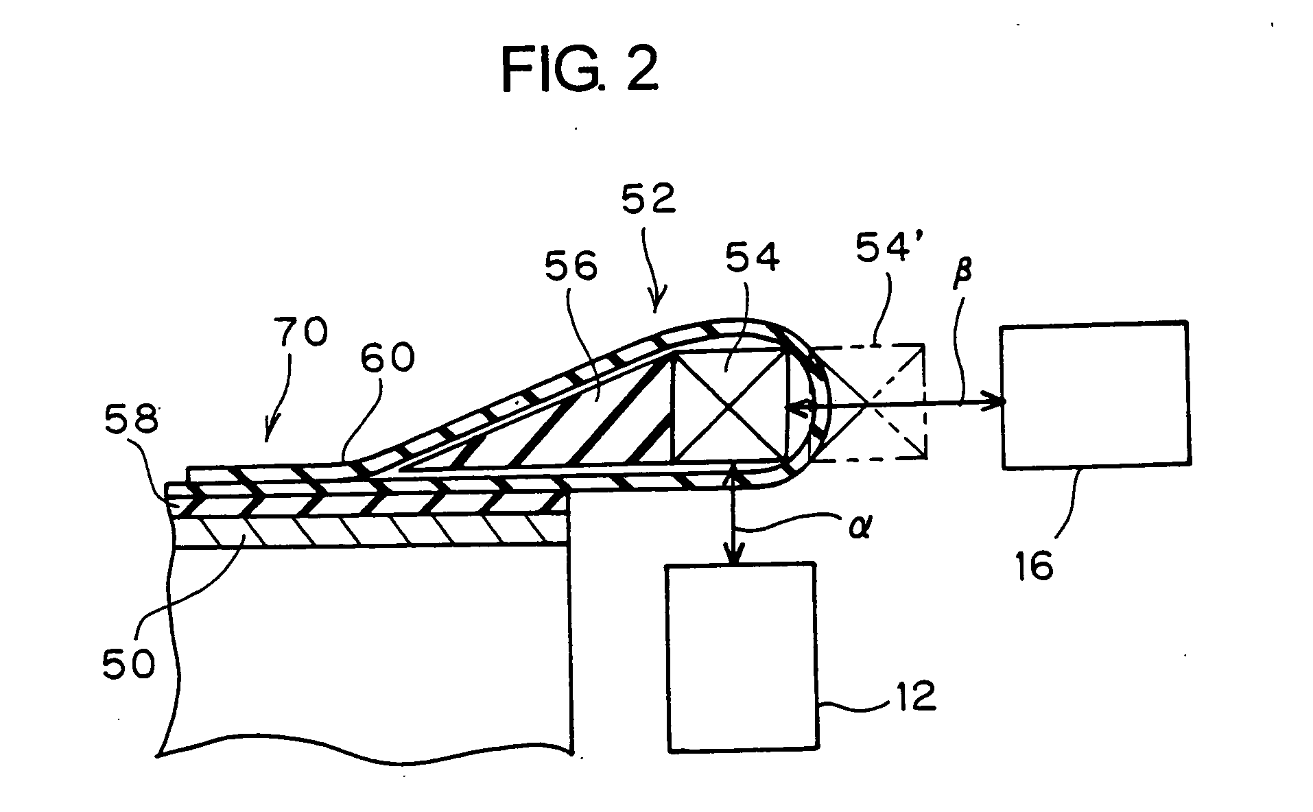
[0027] An inner liner 58 is wound around the tire building drum 50, and a carcass play 60 is then wound around the inner liner 58, whereafter the beads 52 are set on both axial sides of the drum 50. Furthermore, the carcass ply 60 is folded back (or turned up) axially inwards at both edge portions in such a manner as to encompass therein the beads 52, respecti...


PUM

PropertyMeasurementUnit
Distanceaaaaaaaaaa

Abstract

An inspection method for inspecting beads provided on a tire building drum in process of production a pneumatic tire includes measuring a displacement amount in a radial direction on each of the beads lying axially on both sides of the drum with a distance sensor such as an eddy current sensor while rotating the drum, synthesizing displacement amounts so obtained on the beads on both the sides, calculating a harmonic of the displacement amounts in the radial direction of the beads by performing harmonic analysis on a resultant synthesized displacement amount, and determining whether the magnitude of the harmonic so calculated falls within a predetermined range.

Description

CROSS-REFERENCE TO RELATED APPLICATIONS [0001] This application is based upon and claims the benefit of priority from the prior Japanese Patent Application No. 2005-219605, filed on Jul. 28, 2005; the entire contents of which are incorporated herein by reference. BACKGROUND OF THE INVENTION [0002] 1. Field of the Invention [0003] The present invention relates to a method and apparatus for inspecting a pneumatic tire with respect to the eccentricity of beads thereof during production. The invention also relates to a method for producing a pneumatic tire by making use of the inspection method. [0004] 2. Description of the Related Art [0005] Low uniformity of pneumatic tires causes vibrations in a vehicle. Due to this, force variations occurring when they rotate are measured on pneumatic tires after production, and tires showing large force variations are disposed as defectives. [0006] The variability of constituent members of tires being produced that occurs in steps of the tire produ...

Claims


Application Information

Patent Timeline
IPC IPC(8): B29D30/32
CPCB29D30/26G01M17/02
Inventor MORIGUCHI, KINYAWATANABE, HAJIMEYAMASHITA, OSAMU
Owner TOYO TIRE & RUBBER CO LTD
Learn More