Opto-mechanical filter for blending of images from a digital projector

a digital projector and filter technology, applied in the field of projection systems, can solve the problems of not working as well as the light valve lcd or dmd/dlp type micromirror projectors, image often not appearing, objectionable artifacts, etc., and achieve the effect of no tool adjustment, unlimited flexibility, and constant distance from the lens

Active Publication Date: 2007-02-01
CHRISTIE SA
View PDF2 Cites 16 Cited by
  • Summary
  • Abstract
  • Description
  • Claims
  • Application Information

AI Technical Summary

Benefits of technology

[0012] It is an aspect of the present invention to provide an apparatus for optical blending of images from multiple projectors which overcomes the disadvantages of the prior art. According to a preferred embodiment, an optical blending device is mounted to the lens of a projector so as to maintain a constant distance from the lens, where the distance is optimized for proper edge blending and temperature considerations, where variations in width, height, size, sha

Problems solved by technology

Because of the difficulty in ‘butting’ multiple images edge-to-edge, a significant disadvantage of such multiple projector display systems is that the images often do not appear as one single continuous image on the display screen.
Specifically, when displaying a black image, instead of protecting a generally uniformly black area across the entire displayed image the black image tends to brighten in the regions of overlap, giving rise to objectionable artifacts.
Although electronic blending does work for CRT projectors (because the “off” state is completely black), it does not work as well for light valve LCD or DMD/DLP type micromirror projectors when generating black images, which is a matter of importance when projecting quality simulated night scenes (such as required, for example, in aircraft and ship simulators).
Specifically, because the off-state (i.e. black) brightness is a minimum 000 video code value , electronic reduction of light intensity cannot occur since it is already as low as it can go (zero) so it cannot eliminate the bright region of overlap without adversely affecting the contrast ratio of the projection system.
Although this solution effecti

Method used


Image

  • Opto-mechanical filter for blending of images from a digital projector
  • Opto-mechanical filter for blending of images from a digital projector
  • Opto-mechanical filter for blending of images from a digital projector

Examples


Embodiment Construction

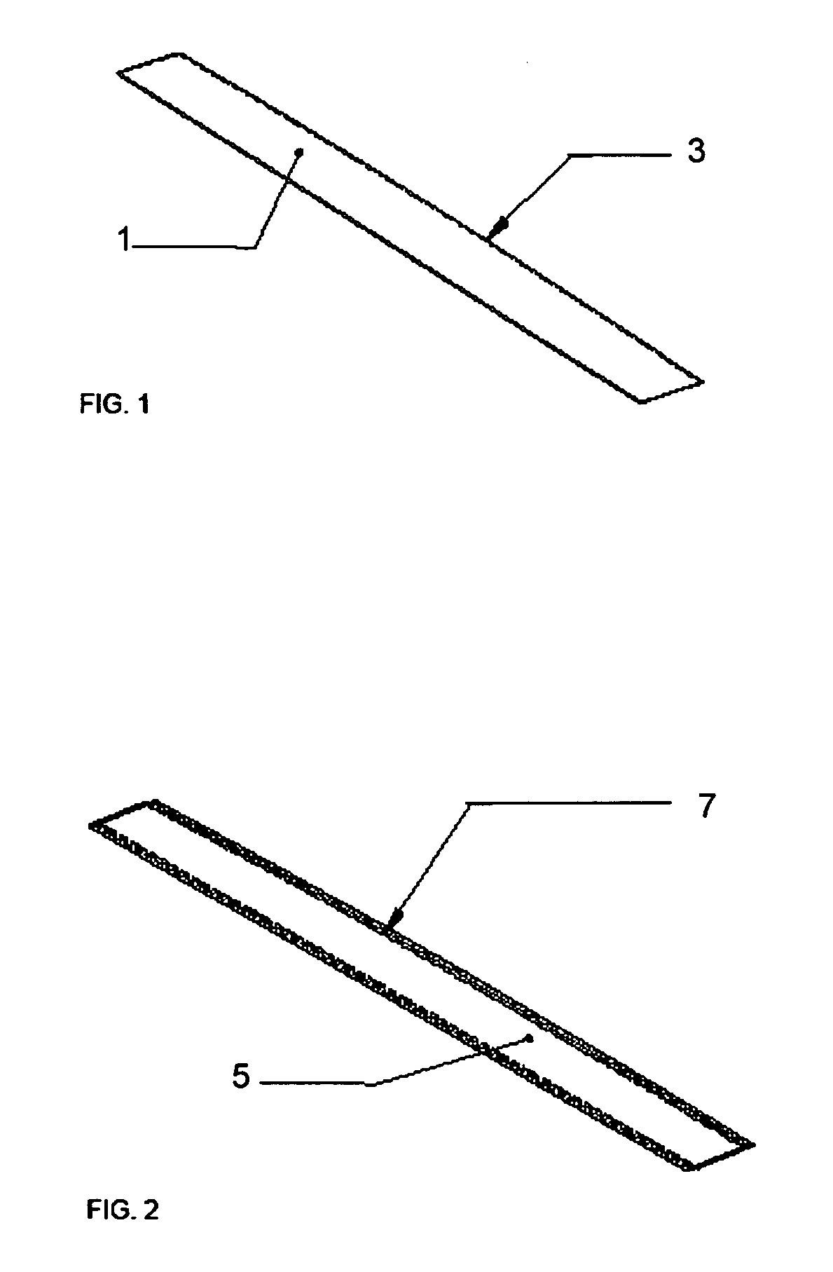
[0026] With reference to FIG. 1, a generally rectangular filter component 1 is shown cut from a commercial transparent polymer (polycarbonate or polyester) film impregnated or coated with a neutral density (ND) color dye, such as described in U.S. Pat. No. 6,531,230 (Weber et al). As is known in the art, one of the longer edges of the filter component is profiled to conform to the shape of the edge of the image as it exits the projection lens of a projector. Typically, the profile follows the shape of a shallow curve 3.

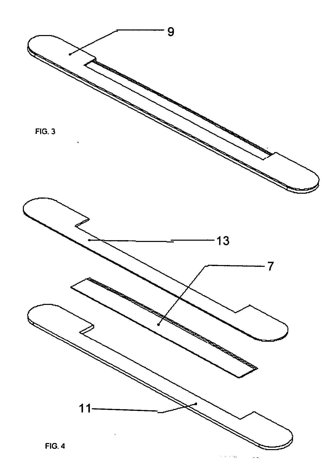
[0027] In FIG. 2, a graduated filter 5 is shown made from layers of cut film filter components of FIG. 1, wherein the curved edges are offset, as indicated by reference numeral 7, to create a ‘stepped’ graduation of the density of the color dye. The width of the cut filter components and graduated stepped offsets may be varied to best conform to the width of the image area to be blended. Also, the number of layers of cut filter components can be varied (three layers ...


PUM


Abstract

A filter mounting apparatus for use with an optical filter placed between a projector lens and screen. The filter mounting apparatus comprises a metallic disk connected to the projector lens, and an assembly magnetically connected to the metallic disk for mounting the optical filter a predetermined distance from the projector lens.

Description

BACKGROUND OF THE INVENTION [0001] 1. Field of the Invention [0002] The present invention is directed to projection systems, and more particularly to an apparatus for blending of images from multiple digital projectors, as are used, for example, in simulation systems with day / night scenarios. [0003] 2. Description of the Related Art [0004] Multiple projection displays are well known in the art, having been used for many years in the film industry to create high-resolution images on large variously shaped screens (e.g. domes, cylinders and toroids, in addition to large flat screens). For example, the CINERAMA system developed in the 1950s used three separate projectors to project three images which were then combined to form a single panoramic image. More recently, video based multiple projector display systems have been used for flight simulators, wherein multiple video screens are placed next to each other to form a large tiled image display. [0005] Because of the difficulty in ‘bu...

Claims


Application Information

Patent Timeline
IPC IPC(8): G03B21/26
CPCG03B21/26G03B21/14
Inventor GILBERT, BRUNOHARRIS, GORDECCLES, BROCK
Owner CHRISTIE SA
Why Eureka
Try Eureka