Method and system for attachment of light emitting diodes to circuitry for use in lighting

a technology of light emitting diodes and circuits, applied in the direction of lighting support devices, lighting and heating apparatus, coupling device connections, etc., can solve the problems of single layer circuit layout and more complex 541 800, and achieve the effect of increasing the contact area of these prongs, increasing the usability of leds, and being easy to attach to circuitry

Inactive Publication Date: 2007-02-01
CHAN TIMOTHY
View PDF19 Cites 57 Cited by
  • Summary
  • Abstract
  • Description
  • Claims
  • Application Information

AI Technical Summary

Benefits of technology

[0007] I propose utilizing the LED leads themselves to create a pair of prongs with a spring-mechanism allowing for easy attachment and removal of the LED from circuitry and a method to increase the contact area of these prongs. The invention involves modifying the leads of the LED itself such as bending and folding or flattening and folding the leads. Hence increasing the usability of the LEDs by making them easier to attach to circuitry while minimizing the increase in manufacturing cost. The current LED-manufacturing process would remain unchanged unlike that of U.S. Pat. No. 6,541,800, which also teaches of a method of heatless attachment. The method shown in U.S. Pat. No. 6,541,800 utilizes a “RCA-type plug” that involves a whole new manufacturing process, which would involve major retooling of current manufacturing lines and render useless current manufacturing capacities. The primary embodiment of the present invention would involve simple subsequent modification of the leads of the LEDs to create a pair of prongs with a spring mechanism and then adding some type of encasement to better secure the contact prongs from forces caused during insertion and unplugging of the LED to its circuitry. Hence current LED-manufacturing capacities can still be utilized.
[0008] A benefit of the present invention is that the LED array circuitry can be kept very simple involving one or more pairs of parallel electrical and thermal conductive channels, which may hold multiple LEDs. Whereas the circuitry of U.S. Pat. No. 6,541,800 would be more complex due to the “RCA-type plug”, where the anode surrounds the cathode making a flat single layer circuit layout impossible, since the electrical paths will have to overlap to make a connection with the cathode that's encircled by the anode.
[0011] This method of attachment to circuitry eliminates the chance of heat damage to the LED that can occur when the LED are soldered.
[0013] A very flexible design of this invention allows the user to easily alter the lighting array color by swapping in different color LEDs without the need of any specialized tools.
[0014] The invention would also allow consumers to configure the LED lighting array as illuminated signs by removing and rearranging the LEDs to create an image.
[0015] LEDs have been around for decades but haven't really taken off in the consumer market. The present invention will hopefully help expand the use of LEDs to replace other lighting. LED save energy compared with incandescent and protect the environment compared with fluorescent, which contain mercury. Further objects and advantage of my invention will become apparent from a consideration of the diagrams and ensuing description.

Problems solved by technology

Whereas the circuitry of U.S. Pat. No. 6,541,800 would be more complex due to the “RCA-type plug”, where the anode surrounds the cathode making a flat single layer circuit layout impossible, since the electrical paths will have to overlap to make a connection with the cathode that's encircled by the anode.

Method used


Image

  • Method and system for attachment of light emitting diodes to circuitry for use in lighting
  • Method and system for attachment of light emitting diodes to circuitry for use in lighting
  • Method and system for attachment of light emitting diodes to circuitry for use in lighting

Examples


Embodiment Construction

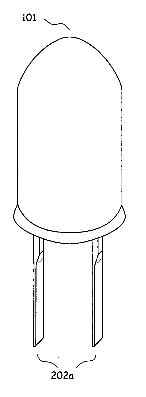
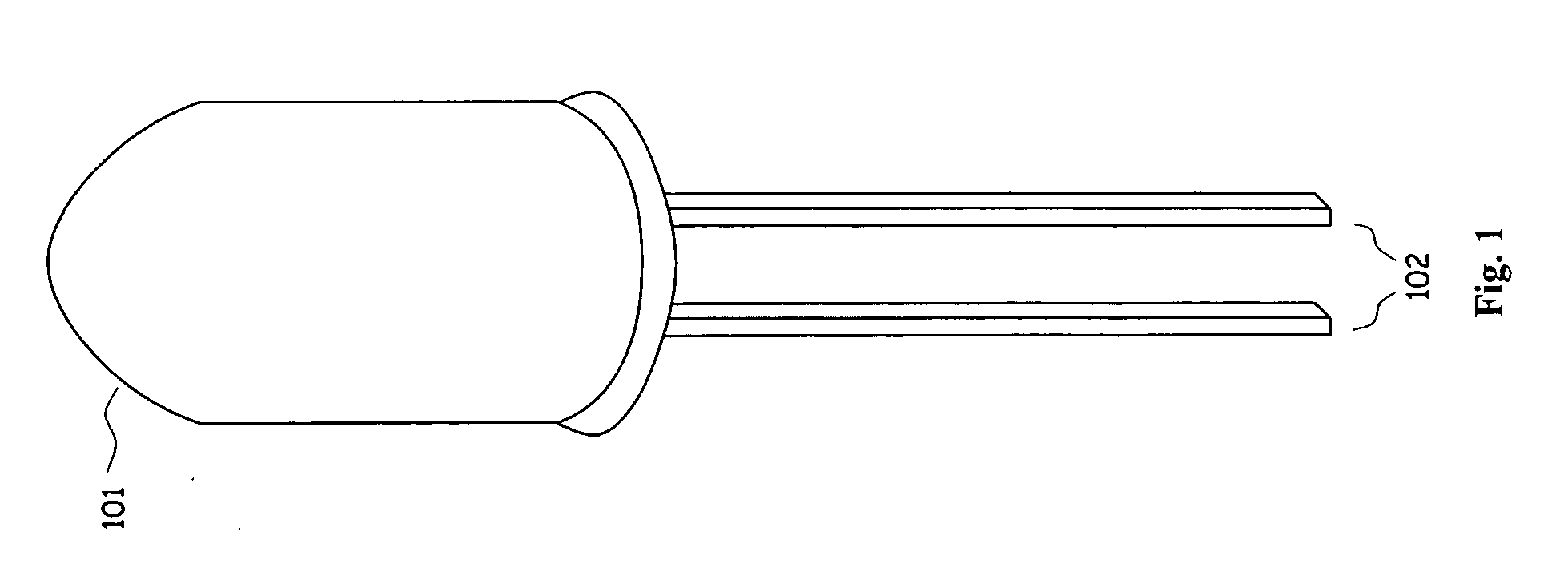
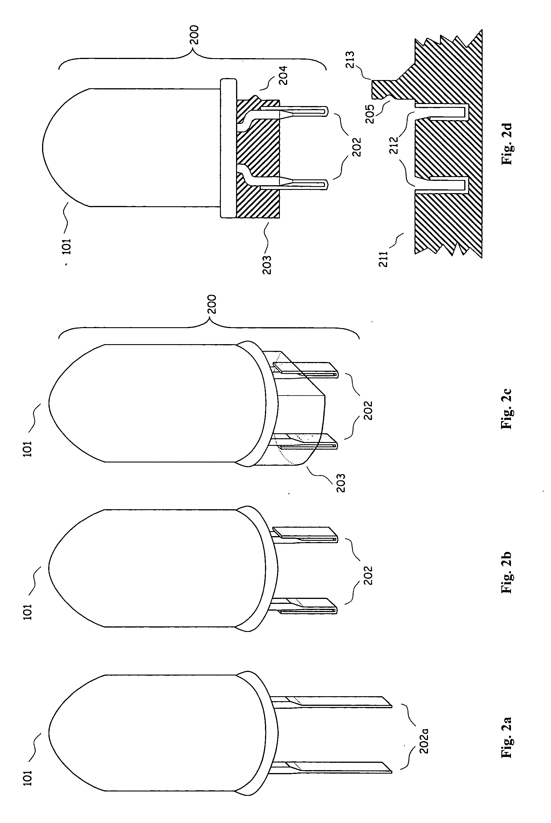
[0038] A common LED is shown in FIG. 1 before any modification with a pair of leads both an anode terminal and a cathode terminal denoted by 102 and a LED package denoted by 101. In the preferred embodiment the LED 101 has both its leads 102 flattened to increase its surface area as shown by FIG. 2a both the flattened anode and cathode leads are denoted by 202a. The leads are then folded as denoted by 202 in FIG. 2b to form a pair of spring prongs. The folds in prongs 202 allows for some give or compression that helps ensure sufficient contact with a corresponding socket without having to manufacture the prongs nor its corresponding socket to very tight tolerances hence minimizing the cost of manufacturing and assembly. The pair of prongs 202 can then be further secured by adding some type of encasement denoted by 203 right below the base as in FIG. 2c the entire finished LED is denoted by 200. The encasement 203 can be mold on using plastic, resin, or other materials or pre-made in...


PUM


Abstract

A method and system for attaching LEDs to circuitry which would protect the LEDs from heat damage and allows for individual LEDs to be removed.

Description

CROSS-REFERENCE TO RELATED APPLICATIONS [0001] This is a continuation-in-part of application Ser. No. 10 / 969,686 filed Oct. 20, 2004STATEMENT REGARDING FEDERALLY SPONSORED RESEARCH OR DEVELOPMENT [0002] Not applicable REFERENCE TO A MICROFICHE APPENDIX [0003] Not applicable BACKGROUND OF INVENTION [0004] In the past LEDs were mainly used as status indicator lights in electronics, but with the vast improvements in technology—increasing the efficiency and the lifespan while reducing cost—LEDs have been put to many more uses. Multiple LEDs can easily be assembled together into an array, by soldering the LEDs together into a circuit, which can then be use to replace fluorescent lights and incandescent light bulbs, as respectively shown by U.S. Pat. No. 6,762,562 “Tubular housing with light emitting diodes” and U.S. Pat. No. 6,580,228 “Flexible substrate mounted solid-state light sources for use in line current lamp sockets”. LED arrays can be put to multitude of lighting uses given the ...

Claims


Application Information

Patent Timeline
Patent Type & Authority Applications(United States)
IPC IPC(8): F21V1/00
CPCF21K9/00H01R33/09H05K3/107H05K3/308H05K3/325H05K2201/09472Y10S362/80H05K2201/10106H05K2201/10651H05K2201/10765F21V19/0025F21V19/042F21Y2101/02H05K2201/09981F21V19/04F21Y2105/10F21Y2107/00F21Y2107/30F21Y2115/10
Inventor CHAN, TIMOTHY
Owner CHAN TIMOTHY
Why Eureka
Try Eureka