Communication method, radio terminal and base station

a communication method and radio terminal technology, applied in the field of communication methods, can solve the problems of affecting the transmission speed of packets, so as to prevent packet collision

Active Publication Date: 2007-02-01
MITSUBISHI ELECTRIC CORP
View PDF5 Cites 21 Cited by
  • Summary
  • Abstract
  • Description
  • Claims
  • Application Information

AI Technical Summary

Benefits of technology

[0014] A communication method according to the present invention, which is a communication method for a carrier-sense-multiple-access (CSMA) network including a radio terminal and a base station to which the radio terminal belongs and supports request-to-send/clear-to-send (RTS/CTS) to prevent a collision of packets due to a hidden terminal, includes: RTS-transmitting including the base station transmitting a request-to-send (RTS) fra

Problems solved by technology

In this communication system, however, there are cases that a transmission signal from another radio terminal cannot be directly received, such as a case that the radio terminals are located with such a distance therebetween that radio waves do not reach, or a case that there is an obstacle, which blocks radio waves, between the radio terminals.
Since the carrier sense does not work effectively between the radio terminals corresponding to the hidden terminals, there is a case that one terminal starts transmission of a wireless packet, while the other is transm

Method used


Image

  • Communication method, radio terminal and base station
  • Communication method, radio terminal and base station
  • Communication method, radio terminal and base station

Examples


first embodiment

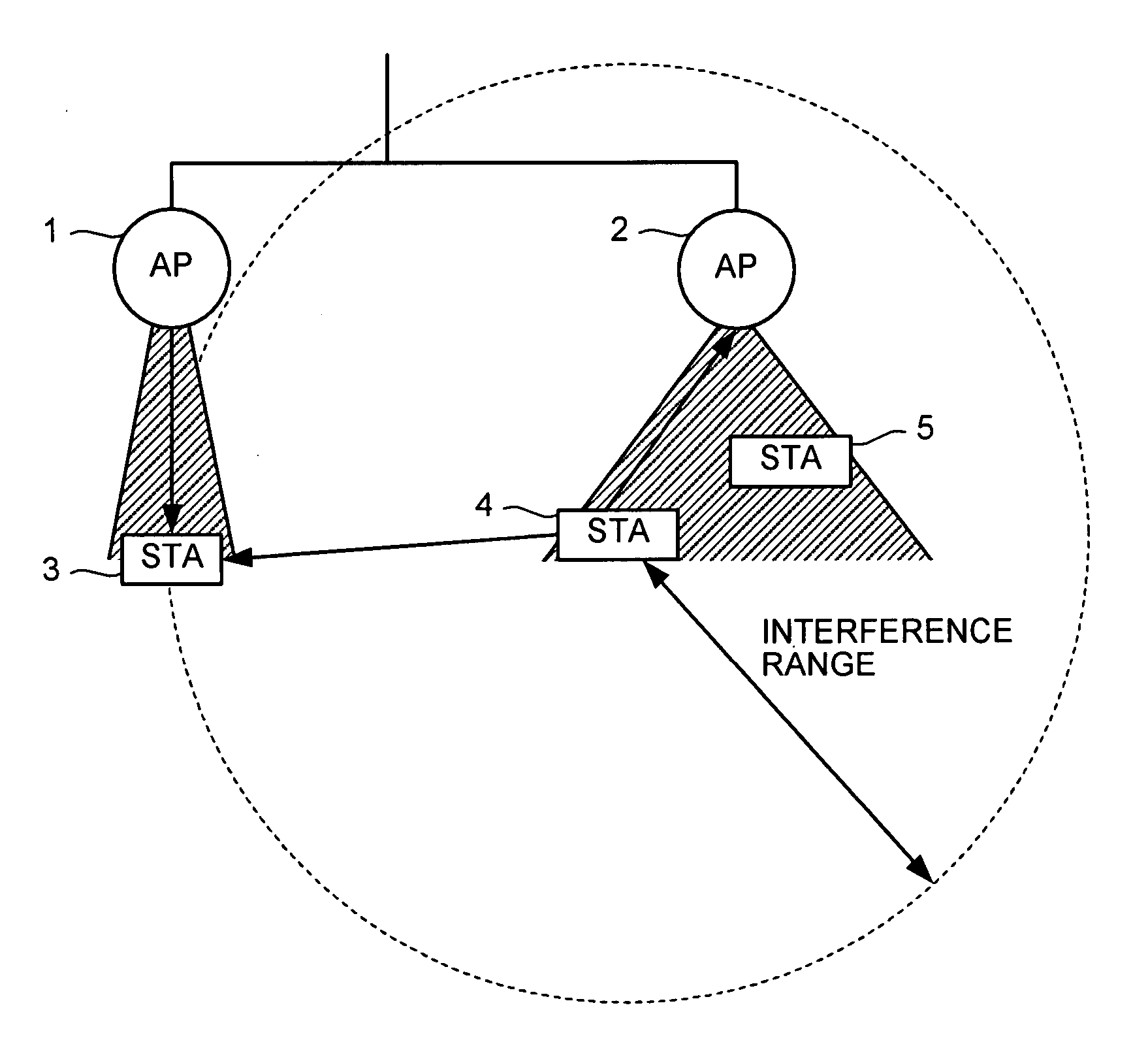
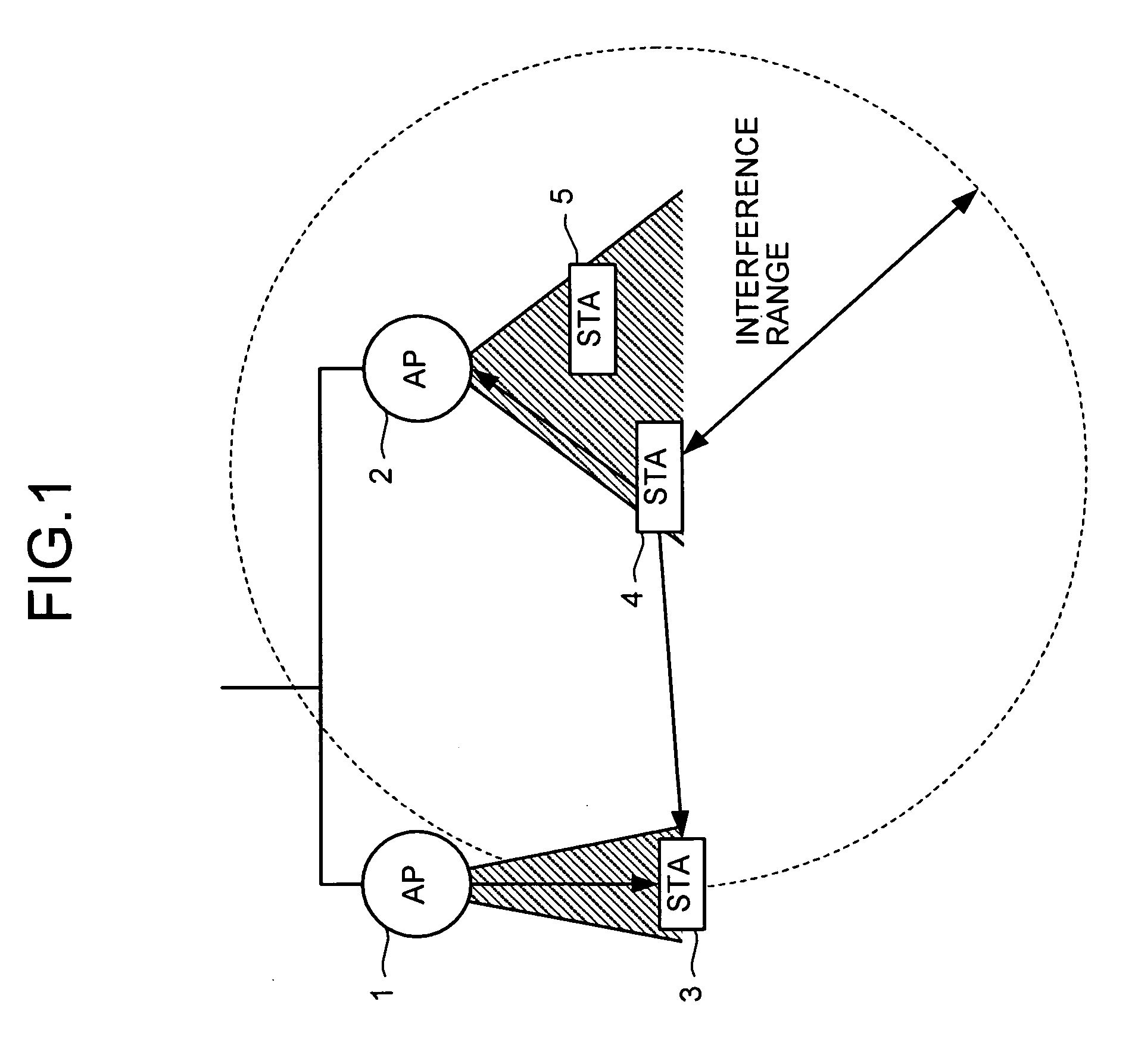
[0030]FIG. 1 depicts the configuration of a communication system capable of realizing the communication method according to the present invention, in which the communication status between a base station (AP) and a radio terminal (STA) is shown. In this communication system, a case that packet communication is carried out in the state that an STA3 belongs to an AP1, and an STA4 and an STA5 belong to an AP2 is assumed. The STA4 is located in the communication range of the STA3, and the STA3 is located in an interference range of the STA4.

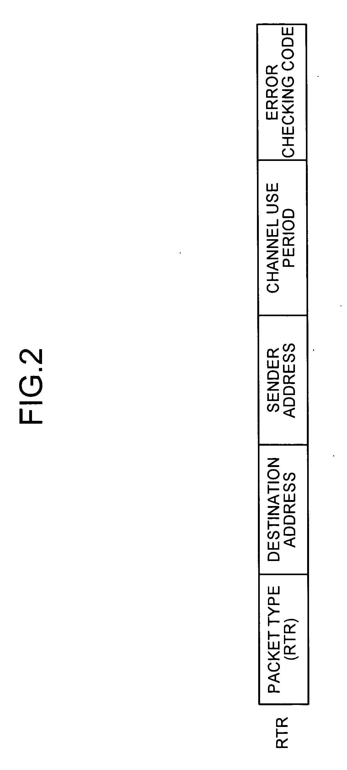
[0031]FIG. 2 depicts a request-to-receive (RTR) format according to a first embodiment of the present invention. The RTR frame includes a packet type field for discriminating the packets (RTR, RTS, and CTS) from each other, a destination address field, a sender address field, a channel use period field indicating the use period of a channel by the wireless packet, and an error-checking-code field added with a calculation result for checking a bit er...

second embodiment

[0045] A communication method according to a second embodiment of the present invention will now be explained. Since the configuration of the communication system is the same as that of FIG. 1 in the first embodiment, like reference numerals are designated with like parts, and explanation thereof is omitted. The respective frame formats used in the second embodiment are the same as those of FIGS. 2, 3, and 4 in the first embodiment.

[0046] The communication method according to the second embodiment will be explained specifically, with reference to the accompanying drawings. FIG. 6 depicts the communication method according to the second embodiment only the operation different from that of the first embodiment will be explained below.

[0047] Since the STA4 could not transmit the CTS frame due to the influence of the hidden terminal, in spite of having received the RTS frame from the AP2 in the past (steps S6 and S8), the STA4 now in the transmission-enabled state in the processing at...

third embodiment

[0051] A communication method according to a third embodiment of the present invention will be explained next. FIG. 7 depicts the configuration of a communication system capable of realizing the communication method according to the present invention, wherein the communication status between the AP and the STA, and the communication status of the AP using the same frequency are shown. In this communication system, a case that packet communication is carried out in the state that the STA3 belongs to the AP1, and the STA4 and the STA5 belong to the AP2 is assumed. The AP2 is located in the communication range of the STA3, and the STA3 is located in the interference range of the AP2. The respective frame formats used in the third embodiment are the same as shown in FIGS. 2, 3, and 4 in the first embodiment.

[0052] The communication method according to the third embodiment will be explained specifically with reference to the accompanying drawings. FIG. 8 depicts the communication method...


PUM


Abstract

A communication method for a CSMA network including a radio terminal and a base station supporting RTS/CTS, includes: the base station transmitting and RTS frame to the radio terminal during a transmission-suspend-period in which the radio terminal suspends transmission to prevent a collision of packets; the radio terminal transmitting an RTR frame to the base station after the transmission-suspend-period has elapsed; and the base station transmitting a date frame to the radio terminal in response to the RTR frame.

Description

TECHNICAL FIELD [0001] The present invention relates to a communication method for a digital radio communication system adopting carrier-sense multiple access (CSMA), which is one of the random access technologies, and more specifically, the invention relates to a communication method capable of avoiding a collision of wireless packets due to the influence of a hidden terminal. BACKGROUND ART [0002] The conventional communication method will be explained first. The CSMA, which is one of the random access technologies, is adopted, for example, in a communication system performing wireless packet communication and the like. In the CSMA, a plurality of radio terminals constituting the system performs carrier-senses for a radio channel prior to wireless packet transmission. When it is recognized that the channel is being used (channel busy), transmission of the wireless packet is suspended, and thereafter, when it is recognized that the channel is not being used (channel idle), the wire...

Claims


Application Information

Patent Timeline
IPC IPC(8): H04Q7/00H04L12/413H04L12/28H04L29/08H04W74/04H04W74/08H04W76/04H04W84/12H04W88/02H04W88/08
CPCH04W74/0816H04W88/08H04W76/04H04W76/20
Inventor NAGAI, YUKIMASASUGA, HIROYOSHI
Owner MITSUBISHI ELECTRIC CORP
Why Eureka
Try Eureka