Method of increasing the capacity of enhanced data channel on uplink in a wireless communications systems

a wireless communication system and data channel technology, applied in the field of wireless communications, can solve the problems of inability to determine whether ue is transmitting a new data packet or a previously transmitted data packet, and the packet size of e-dpdch can still vary, and achieve the effect of greatly increasing the capacity of applications using the enhanced uplink data channel and significantly reducing the power of e-dpcch

Inactive Publication Date: 2007-02-01
LUCENT TECH INC
View PDF36 Cites 112 Cited by
  • Summary
  • Abstract
  • Description
  • Claims
  • Application Information

AI Technical Summary

Benefits of technology

[0007] In accordance with an embodiment of the present invention, the required E-DPCCH power is significantly reduced and the capacity for applications using the enhanced uplin

Problems solved by technology

However, in the initial stage of the communication between NodeB and UE, the E-DPDCH packet size can still vary due to a lack of so called “robustness

Method used


Image

  • Method of increasing the capacity of enhanced data channel on uplink in a wireless communications systems
  • Method of increasing the capacity of enhanced data channel on uplink in a wireless communications systems
  • Method of increasing the capacity of enhanced data channel on uplink in a wireless communications systems

Examples


first embodiment

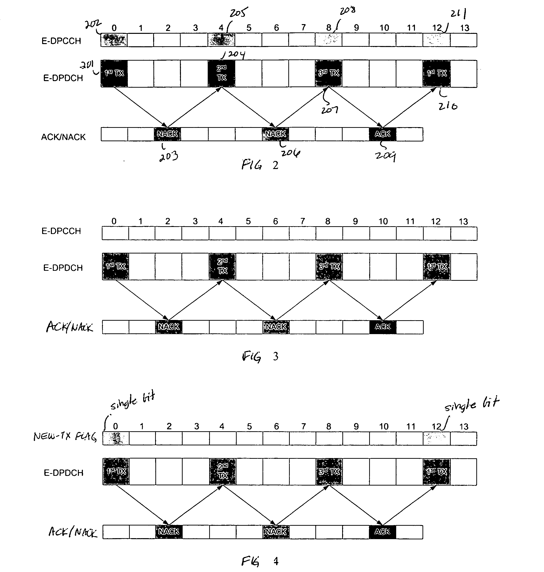
[0020]FIG. 3 shows a modification the timing diagram of FIG. 2 in accordance with this first embodiment where E-DPCCH is totally turned off when the E-DPDCH packet size has reached the default packet size for a VolP-like application. As was noted above, this timing diagram, as in FIG. 2, is for a TTI of 10 ms but is equally applicable when TTI is equal to 2 ms.

[0021] When E-DPCCH is totally switched off as per this first embodiment, NodeB processing by necessity becomes more complicated. As previously noted, the two most important parameters values the E-DPCCH channel conveys to NodeB are packet size and redundancy version. While the NodeB knows to use the default packet size for VolP-like applications when the E-DPCCH is switched off, it remains blind on whether UE is transmitting a new data packet or retransmitting a previously transmitted data packet. Therefore, NodeB needs to decode each data packet received on E-DPDCH multiple times based on all the possible redundancy versions...

second embodiment

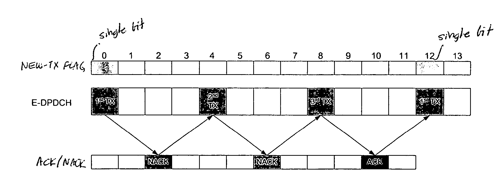
[0029]FIG. 4 shows the timing relationship between E-DPCCH, the one-bit new-tx flag, E-DPDCH, and the ACKs / NACKs received by the UE in accordance with the As can be noted, E-DPCCH is turned off. The single-bit new-tx flag is transmitted only during frames 0 and 12 when E-DPDCH is simultaneously making a new transmission. No flag and no E-DPCCH are transmitted during frames 4 and 8 when second and third transmissions of the E-DPDCH frame are made in response to receiving NACKs in frames 2 and 6, respectively.

[0030] As compared with the first embodiment, the second embodiment simplifies the NodeB implementation by eliminating the need to decode the same E-DPDCH frame multiple times at the expense of consuming minimum air interface resources to transmit the new-tx flag. The new-tx flag could be transmitted from UE to NodeB by either adding a specific code word on the current E-DPCCH or by means of a separate physical code channel. Power consumption for transmitting a single bit only f...


PUM


Abstract

In a UMTS wireless communication system, when the packet size on the enhanced dedicated physical data channel (E-DPDCH) on the uplink from a UE to a NodeB reaches a converged default packet size, the corresponding dedicated physical control channel (E-DPCCH) is turned off. The NodeB uses the default packet size to decode the frame received on the E-DPDCH using each possible redundancy version. Alternatively, the E-DPCCH is turned off and a new transmission flag is transmitted by the UE only when a new frame is transmitted by the UE. NodeB then uses the presence or absence of that flag in conjunction with the absence of E-DPCCH to determine which redundancy version is to be assumed in decoding the frame received on E-DPDCH.

Description

TECHNICAL FIELD [0001] This invention relates to wireless communications. BACKGROUND OF THE INVENTION [0002] A wireless communications network typically includes a variety of communication nodes coupled by wireless or wired connections and accessed through different types of communications channels. Each of the communication nodes includes a protocol stack that processes the data transmitted and received over the communications channels. Depending on the type of communications system, the operation and configuration of the various communication nodes can differ and are often referred to by different names. Such communications systems include, for example, a Code Division Multiple Access 2000 (CDMA2000) system and a Universal Mobile Telecommunications System (UMTS). [0003] Third generation wireless communication protocol standards (e.g., 3GPP-UMTS, 3GPP2-CDMA2000, etc.) may employ a dedicated traffic channel in the uplink (e.g., a communication flow between a mobile station (MS) or U...

Claims


Application Information

Patent Timeline
IPC IPC(8): H04L12/56H04B1/707H04J13/00H04W28/06H04W28/18H04W48/08H04W76/04
CPCH04L1/0025H04L1/0039H04L1/0046H04L1/0075H04W76/04H04L1/1816H04W28/06H04W28/18H04W48/08H04L1/08H04W76/20H04L5/0055
Inventor BACHL, RAINER WALTERRAO, ANIL M.SCHACHT, MIRKOYE, HENRY HUI
Owner LUCENT TECH INC
Why Eureka
Try Eureka