Edge densification for film boiling process

a technology of densification and film boiling, which is applied in the direction of solid-state diffusion coating, electric/magnetic/electromagnetic heating, friction lining, etc., can solve the problem of increasing the electric consumption, high overall electric consumption compared to the standard l-cvi process, and rapid blockage of the surface porosity of the preform

Active Publication Date: 2012-04-24
SAFRAN LANDING SYSTEMS
View PDF19 Cites 0 Cited by
  • Summary
  • Abstract
  • Description
  • Claims
  • Application Information

AI Technical Summary

Benefits of technology

[0027]Another aspect of the present invention relates to combining CVD and film boiling such that most of the material is densified by film boiling, and then, before the preform is fully densified, the level of liquid precursor in the film boiling reactor is decreased so the preform is no longer immersed in the liquid precursor. The densification thereafter becomes a gaseous CVD process. Densification can be finished using vapor from the liquid precursor that remains in the reactor chamber. The required final power is greatly decreased and the edge densification is improved.

Problems solved by technology

However, conventional CVI frequently causes rapid blockage of the surface porosity of the preform before interior portions of the preform are adequately densified.
For example, in the case of densification using cyclohexane as a precursor, an interior temperature of the porous article during densification may be between about 900° C. and about 1200° C. although the surrounding liquid cyclohexane temperature is only about 80° C. to about 82° C. As a result, overall electric consumption is high compared to the standard l-CVI process.
This increases the electric consumption and necessitates costly power supplies able to deliver the required heating.
However, this approach necessary results in a certain level of material waste.
In addition, when thicker preforms are used, infiltration as a whole becomes relatively more difficult.
This can cause the core part of the preform to be insufficiently densified because the precursor has difficulty in reaching the interior of the preform.
In certain situations, this approach cannot be used.
However, because of the low permeability of the PTFE textile (compared to the permeability of carbon felt, for example) the transfer of precursor to interior parts of the preform is hindered.
This can result in an insufficiently densified core (sometimes referred to as a “hollow” core).

Method used


Image

  • Edge densification for film boiling process
  • Edge densification for film boiling process
  • Edge densification for film boiling process

Examples


Embodiment Construction

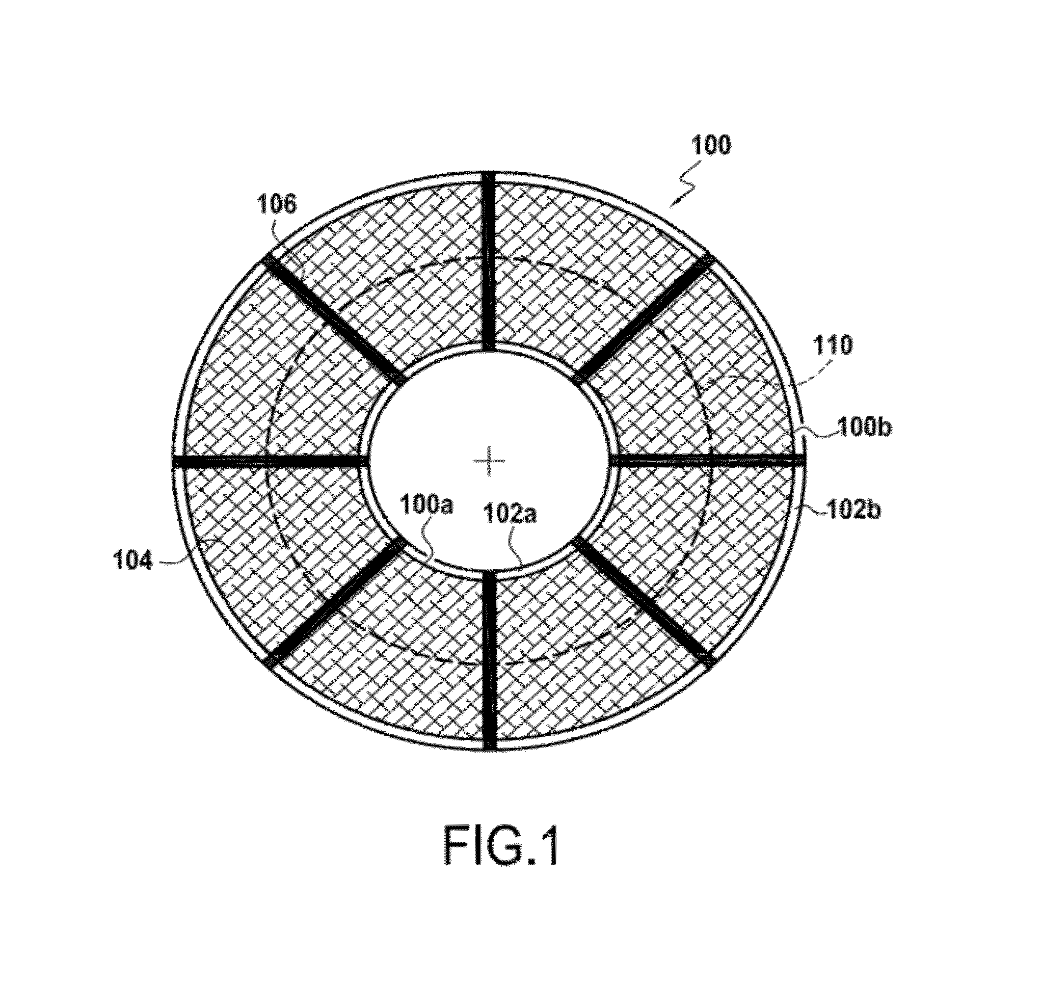
[0037]1. Mesh material having high open porosity

[0038]In a conventional film boiling densification process, improvement of densification at the edges (surface or peripheral) compared to the conventional art is a concern. To address this issue according to conventional approaches generally requires a high power level during a film boiling process.

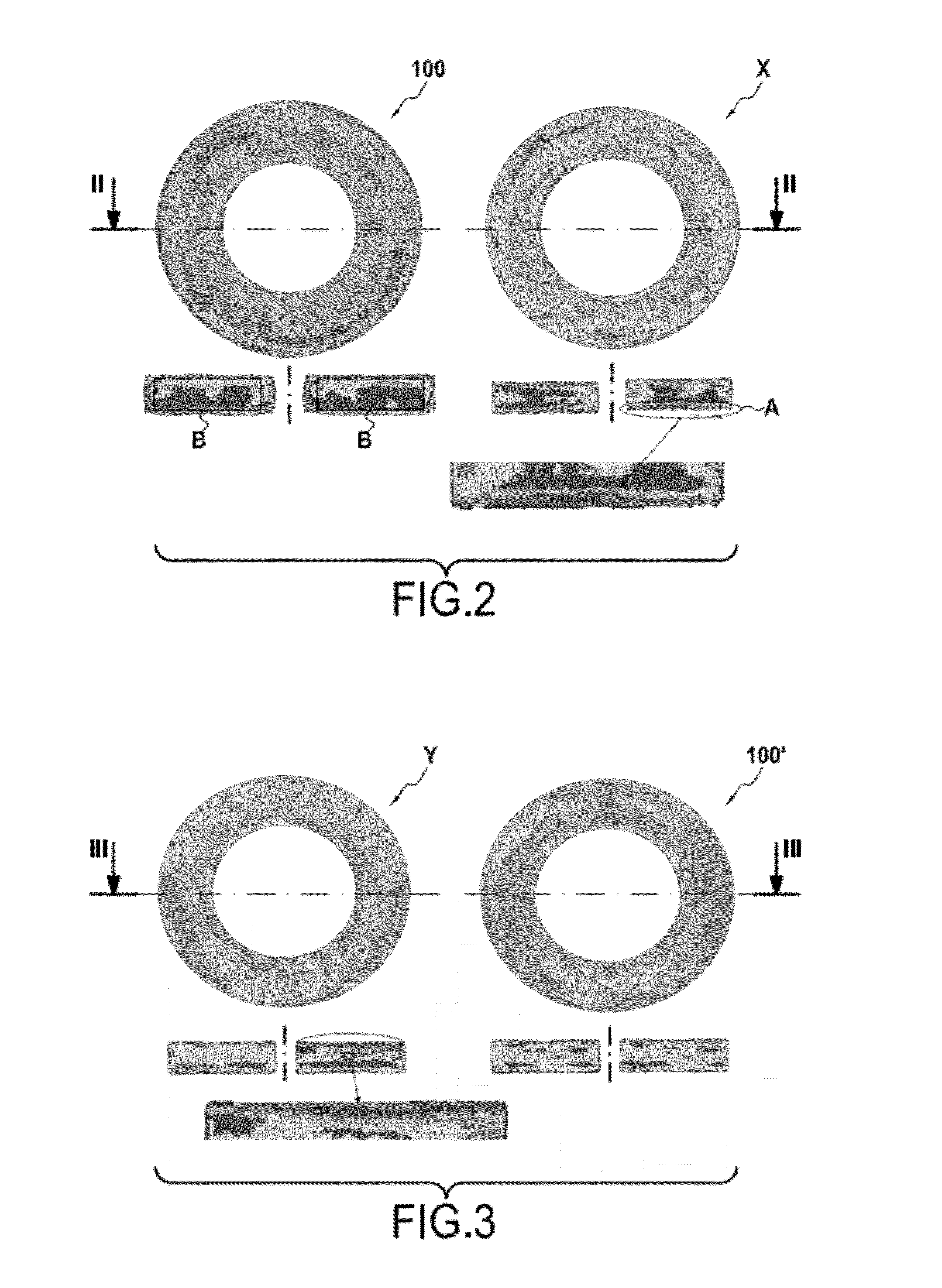
[0039]For example, to density a 20″ carbon brake disk (densification front moved substantially up to the surface of the brake disk) may require more than 70 W / cm2 at the end of the cycle when the part is heated with direct coupling. One way to decrease this power consumption is to physically insulate the preform. However, insulating the preform very often affects homogeneity of the densification. In particular, wrapping a preform with insulation such as carbon felt or a PTFE textile as described in U.S. Pat. Nos. 6,994,886 and 5,981,002 can have a negative impact on the core densification.

[0040]As is generally known, the high thermal gradien...


PUM

PropertyMeasurementUnit
porosityaaaaaaaaaa
porosityaaaaaaaaaa
poweraaaaaaaaaa

Abstract

A method and apparatus are disclosed for improving densification of porous substrate using a film boiling process. In particular, the disclosed method and apparatus permit more complete densification of a substrate (i.e., densification closer to the surface of the substrate) by providing a sort of barrier that reduces cooling of the surface of the substrate being densified caused by contact with the relatively cool boiling liquid precursor of the densifying material, such as carbon. In particular, contact between the substrate and the liquid precursor is reduced using one or both of physical barriers (such as a mesh material) or structures that promote the formation of an insulating gaseous layer between the substrate and the liquid precursor (such as a plate closely spaced apart from the surface of the porous substrate).

Description

PRIORITY BENEFIT[0001]The present application claims priority benefit of U.S. provisional application No. 60 / 972,905, filed on Sep. 17, 2007, the entire content of which is incorporated herein by reference in all venues and jurisdictions where incorporation by reference is permitted.FIELD OF THE INVENTION[0002]The present invention relates to densifying porous articles.BACKGROUND OF THE INVENTION[0003]In the field of friction materials, it is generally known to use substrates made from porous materials to manufacture friction members, such as friction brake disks. The manufacture of such friction members generally begins with the construction of a porous preform, such as an annular preform.[0004]The annular preforms can be constructed using several different known methods. For example, carbon fiber fabric plies can be needled together and annular preforms can be cut from the stacked material. The plies may be made, for example, from airlaid fibers or woven fibers. Also, near net sha...

Claims


Application Information

Patent Timeline
Patent Type & Authority Patents(United States)
IPC IPC(8): C23C16/00H05B6/02H05B6/24C23C14/26C23C8/00B05D1/18
CPCF16D69/023C04B35/117C04B35/83C04B2235/3826C04B2235/3873C04B2235/422C04B2235/48C04B2235/483C04B2235/614C04B2235/616
Inventor FILLION, ARNAUD
Owner SAFRAN LANDING SYSTEMS
Why Eureka
Try Eureka