Sewage lift mechanism with remote alarm

a technology of sewage lift and remote alarm, which is applied in the direction of sewer systems, non-positive displacement fluid engines, constructions, etc., can solve the problems of high failure rate of lift station alarm, high false alarm rate, and overflow of sewag

Inactive Publication Date: 2007-02-01
POLINO MIKE
View PDF5 Cites 3 Cited by
  • Summary
  • Abstract
  • Description
  • Claims
  • Application Information

AI Technical Summary

Problems solved by technology

Sewage lift stations are commonly used in buildings where gravity flow sewer systems are not feasible.
When the float or triggering mechanism is inoperable, the pump is never signaled to evacuate the sewage housing and an

Method used


Image

  • Sewage lift mechanism with remote alarm
  • Sewage lift mechanism with remote alarm
  • Sewage lift mechanism with remote alarm

Examples


Embodiment Construction

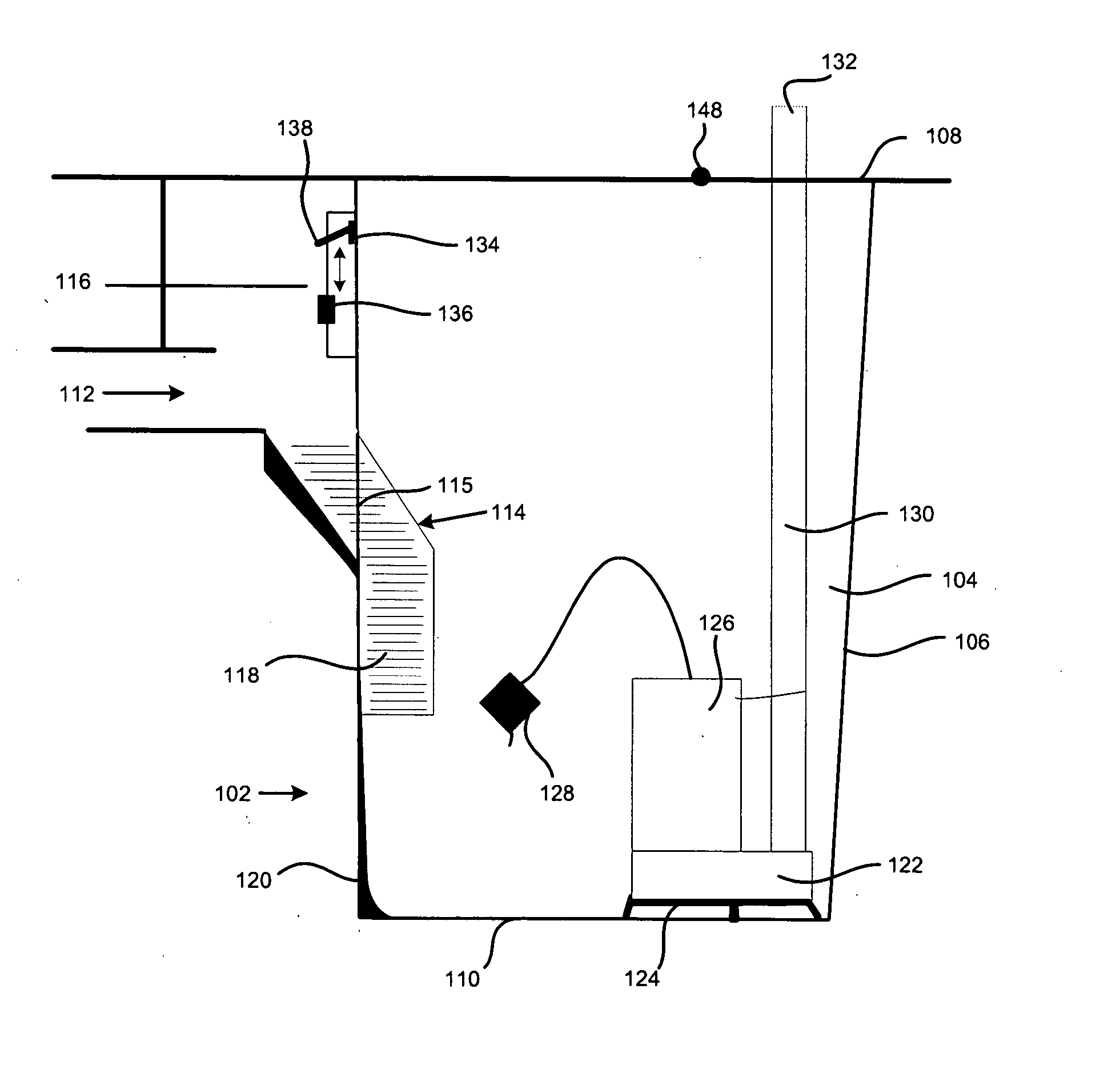
[0013] The present invention relates to a new and novel sewage lift station 102 for accumulating and conveying sewage to a remote destination.

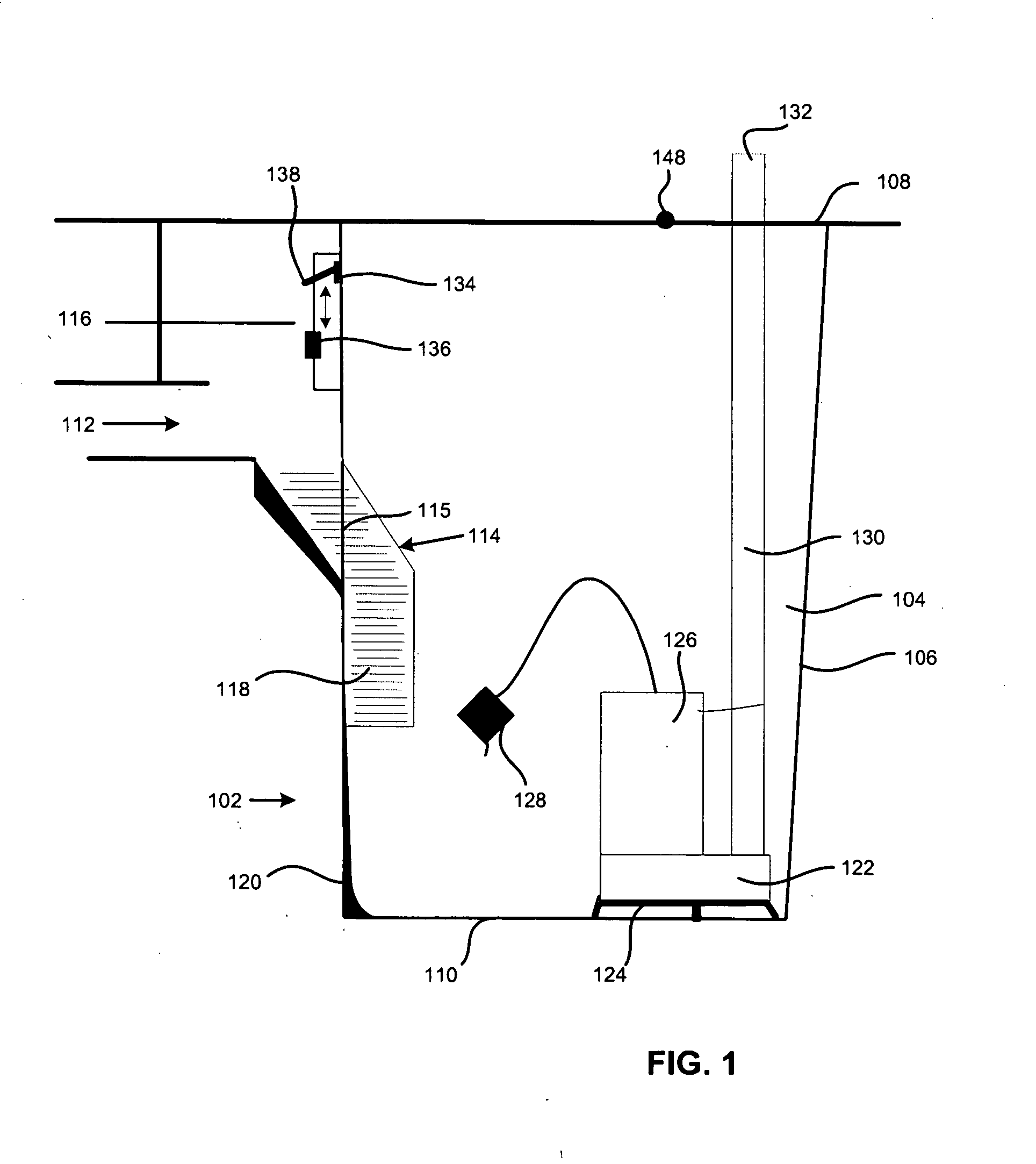
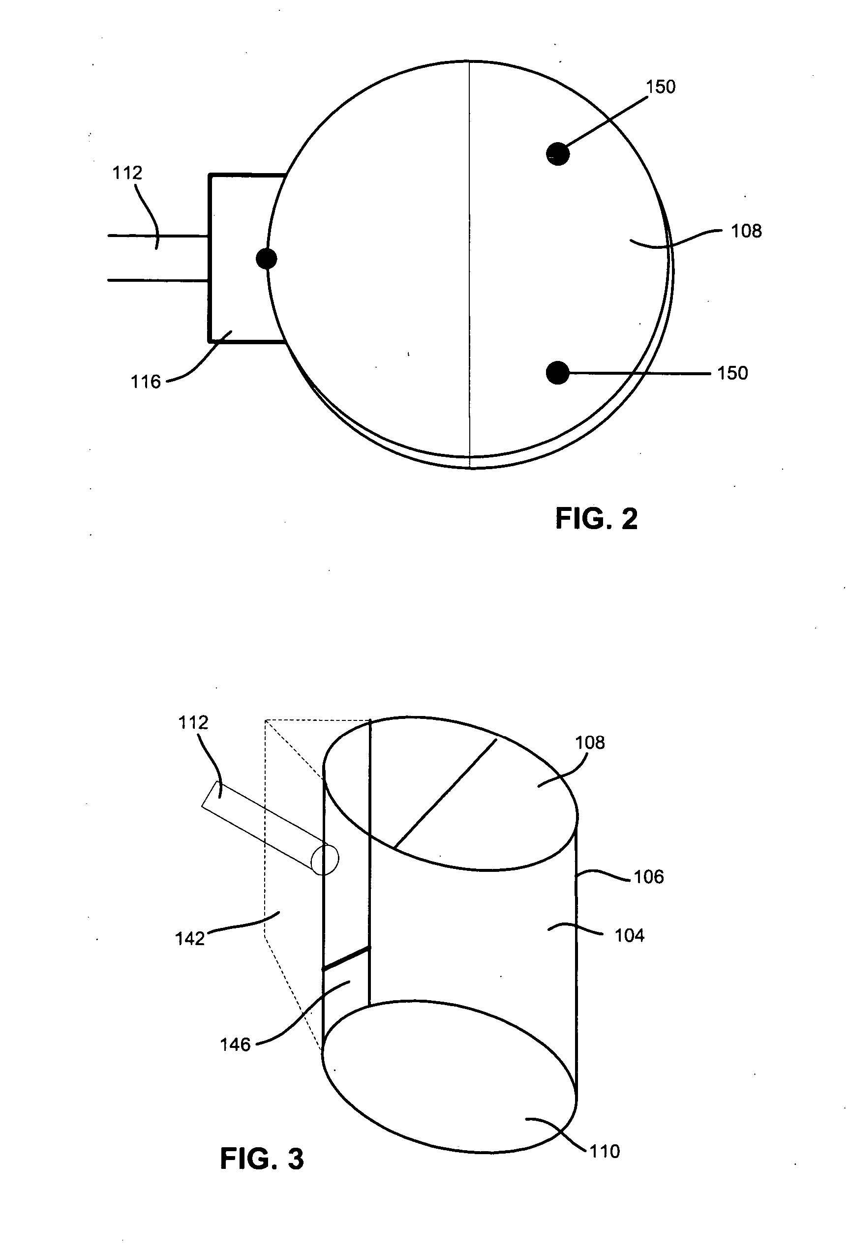
[0014] Referring now generally to FIG. 1, an embodiment of the invention is shown which includes a substantial barrel shape sewage receptacle or housing 104. The housing 104 includes a contiguous wall 106 with a spaced apart top 108 and bottom 110. A sewer inlet pipe 112 is mounted onto the wall 106 of the sewer housing 104. A sewage drop pipe 114 is formed into the wall 106 of the housing 104 adjacent to and generally downward from the inlet pipe 112.

[0015] The sewage drop pipe 114 includes a lower portion 118 which depends generally downward from the side of the housing 104 toward the bottom surface 110 and away from the top surface 108. The sewage drop pipe 114 also includes an upper portion 116 which is oriented generally upward and adjacent the inlet pipe 112. It is preferred that the upper portion 116 of the sewage drop pipe 114 be pos...


PUM


Abstract

The invention is a sewage lift station having a chamber for accumulating sewage and a pump mechanism for expelling sewage to a remote location. A sewage drop pipe is provided which directs sewage entering into the station below a triggering mechanism on the pump thereby eliminating pump failure caused by solids within the sewage dropping onto it. A remote alarm system is provided to signal pump failure.

Description

RELATED APPLICATIONS [0001] This application claims the benefit of priority to U.S. Application No. 60 / 704,115 filed Jul. 29, 2005, which is incorporated herein by reference.BACKGROUND [0002] The present invention generally relates to a sewage lift mechanism for use in residences or commercial buildings configured to reduce the likelihood of mechanical failure and further provided with an audible alarm to signal users of a potential overflow. BACKGROUND OF THE INVENTION [0003] Sewage lift stations are commonly used in buildings where gravity flow sewer systems are not feasible. It is often necessary to forcibly pump sewage from a collection basin or other containment area to a remote sewer line or septic system. One such example would be in a residence with a basement where the basement toilet facilities are positioned below or down gradient the sewer lines. [0004] Where it is necessary to forcibly pump sewage to a remote sewer line, it is common to provide a sewer lift station in w...

Claims


Application Information

Patent Timeline
IPC IPC(8): F04B49/00
CPCE03F5/22F04D13/086F04D15/0218
Inventor POLINO, MIKE
Owner POLINO MIKE
Why Eureka
Try Eureka