Eureka AIR delivers breakthrough ideas for toughest innovation challenges, trusted by R&D personnel around the world.

Ophthalmic device positioning system and associated methods

Active Publication Date: 2007-02-01
ALCON INC
View PDF4 Cites 66 Cited by
  • Summary
  • Abstract
  • Description
  • Claims
  • Application Information

AI Technical Summary

Benefits of technology

[0008] Embodiments of the system and method of the present invention have an advantage that no additional hardware is required if the ophthalmic device already comprises means for imaging the surface of the eye and for capturing that image. An additional element can comprise a software package for computing optimal centering and focal position, and for either indicating a required ophthalmic device movement, or for driving the ophthalmic device position depending upon the presence of an automatic positioning capability.
[0009] In cases in which it is desired for either the software or an operator to interact with the image, it is preferable that features in the image be as sharp as possible, within the limits of the ophthalmic device. Embodiments of the present invention can optimize focus by maximizing the clarity of the features in the image.

Problems solved by technology

Known current approaches to solving the positioning problem are typically subject to error and require intervention by an operator and / or additional hardware.

Method used


Image

  • Ophthalmic device positioning system and associated methods
  • Ophthalmic device positioning system and associated methods
  • Ophthalmic device positioning system and associated methods

Examples


Embodiment Construction

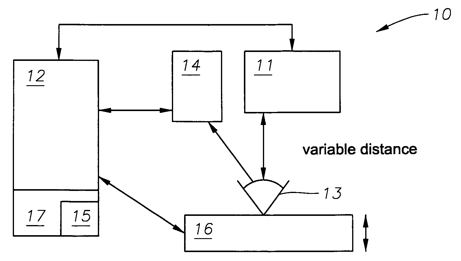
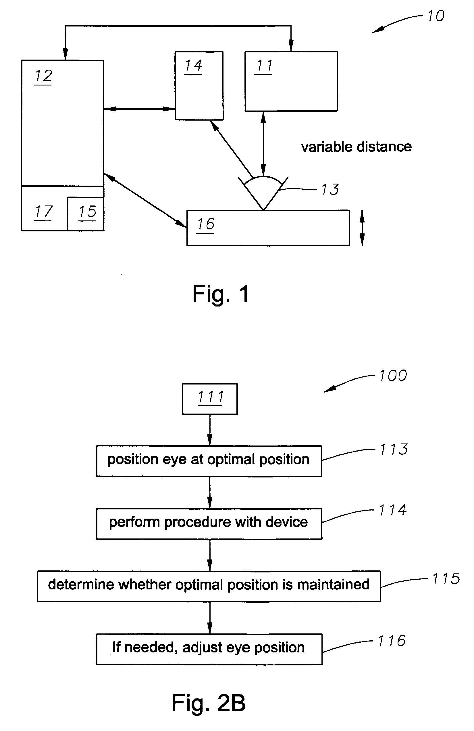
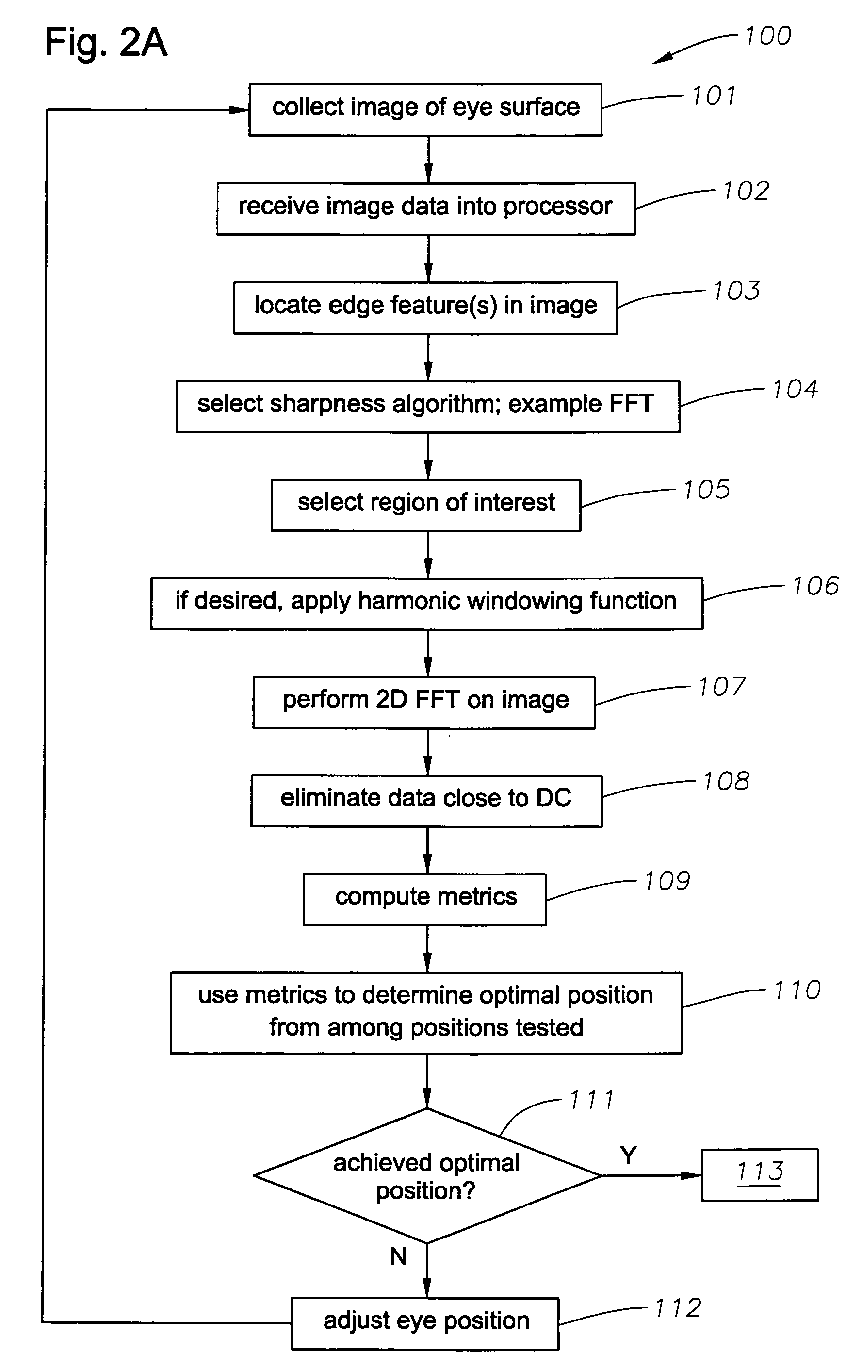
[0018] A description of the preferred embodiments of the present invention will now be presented with reference to FIGS. 1-6C. An exemplary embodiment eye positioning system 10 is depicted schematically in FIG. 1, and an exemplary method 100, in FIGS. 2A and 2B.

[0019] An embodiment 100 of the method for determining an optimal (therapeutically effective) position of an eye relative to an ophthalmic device 11 comprises the step of receiving data into a processor 12 (block 102). The data comprise an image of a surface of an eye 13 that has been collected with, for example, a video camera, digital camera, still camera or frame grabber 14, in communication with the processor 12. The image is collected with the eye at a first position relative to the ophthalmic device 11 (block 101). Ophthalmic device 11 can be, for example, and without limitation, a femptosecond laser microkeratome, a treatment laser, such as an excimer laser, an aberrometer, or any other ophthalmic device as will be kn...


PUM


Abstract

A system and method for determining an optimal position of an eye relative to an ophthalmic device are disclosed. One embodiment of the method includes receiving data comprising an image of a surface of an eye with the eye at a first position relative to an ophthalmic device. An edge feature in the image is located, and a sharpness calculation on the edge feature is performed using a predetermined algorithm to yield a sharpness value. The eye surface is then adjusted to a second position relative to the ophthalmic device, and the previous steps are repeated until the sharpness value is maximized, which is an indication that an optimal eye position has been achieved. An embodiment of the system includes a processor and a software package executable by the processor, the software package adapted to perform the calculations as above. Means are also provided for adjusting the eye surface to a second position relative to the ophthalmic device.

Description

TECHNICAL FIELD OF THE INVENTION [0001] The present invention relates to systems and methods for performing corneal wavefront measurements and laser-assisted corneal surgery, and, more particularly, to such systems and methods for optimizing a focus of the eye undergoing such surgery. BACKGROUND OF THE INVENTION [0002] It is known in the art to perform corneal ablation by means of wavefront-guided refractive laser surgery. Typically a wavefront sensor measures an aberration map and its position relative to anatomical landmarks, which can be intrinsic or externally applied features. Aberration data, sometimes along with geometric registration information, can be transferred directly to a treatment excimer laser, which is typically used to perform the ablation. [0003] In ophthalmic devices, the positioning of a measuring or ablation device a known distance from, and correctly aligned to, an eye, such that the device can be therapeutically effective, is of great importance. In some sys...

Claims


Application Information

Patent Timeline
IPC IPC(8): A61B18/18A61B3/10G01B11/00
CPCA61B3/152A61B3/1015A61B3/10
Inventor CAMPIN, JOHN A.BOWES, JOHN J.
Owner ALCON INC
Why Eureka
Eureka Blog
Learn More