Automated panretinal laser photocoagulation

a panretinal and laser technology, applied in the field of ophthalmic devices, can solve the problems of manual treatment with a significant degree of operator dexterity, significant health problems, and impaired vision,

Inactive Publication Date: 2007-02-01
EISENBERG ELLIOT S +1
View PDF10 Cites 27 Cited by
  • Summary
  • Abstract
  • Description
  • Claims
  • Application Information

AI Technical Summary

Problems solved by technology

Diabetes Mellitus is a significant health problem.
In fact, this pathology is the most frequent cause of blindness among adults aged 20-74 years.
Derangement of the underlying retina leads to visual loss and blindness.
All three require manual treatments with a significant degree of operator dexterity.
The procedure (PRP) is time consuming for both the patient and physician.
An extremely small variation in spatial position can leave the treating surgeon out of focus or in the wrong locality for treatment.
Likewise, a subtle shift in eye position or lid position by the patient can prevent adequate treatment As in the slit-lamp format triggering the laser is usually by a foot activated switch.
It is not designed for office usage as it requires intraocular penetration.
Accidentally contacting the retinal surface with the probe tip can result in hemorrhage or retinal holes.
Therefore it is the least utilized mechanism for panretinal delivery and not intended for widespread usage.
While prior inventors have addressed a few of these issues none have achieved the majority of these objectives.
Although proposing an optical mechanism to reduce treatment times they fail to make a huge reduction in treatment time.
And while the procedure duration may be reduced somewhat with a plurality of beams burning the retina in a single application, it would likely increase the pain of each individual bum and thus mandate anesthesia.
Furthermore, the apparatus does not lessen the need for a high degree of user coordination in each of the delivery formats.
Each is not conducive to treating large numbers of patients with proliferative diabetic retinopathy or other diseases requiring PRP.
Each fails to minimize the complications of panretinal photocoagulation which are well documented.
And finally, each is not a time efficient way of providing treatment.

Method used


Image

  • Automated panretinal laser photocoagulation
  • Automated panretinal laser photocoagulation
  • Automated panretinal laser photocoagulation

Examples


Embodiment Construction

—PREFERRED EMBODIMENT—FIGS. 1-10

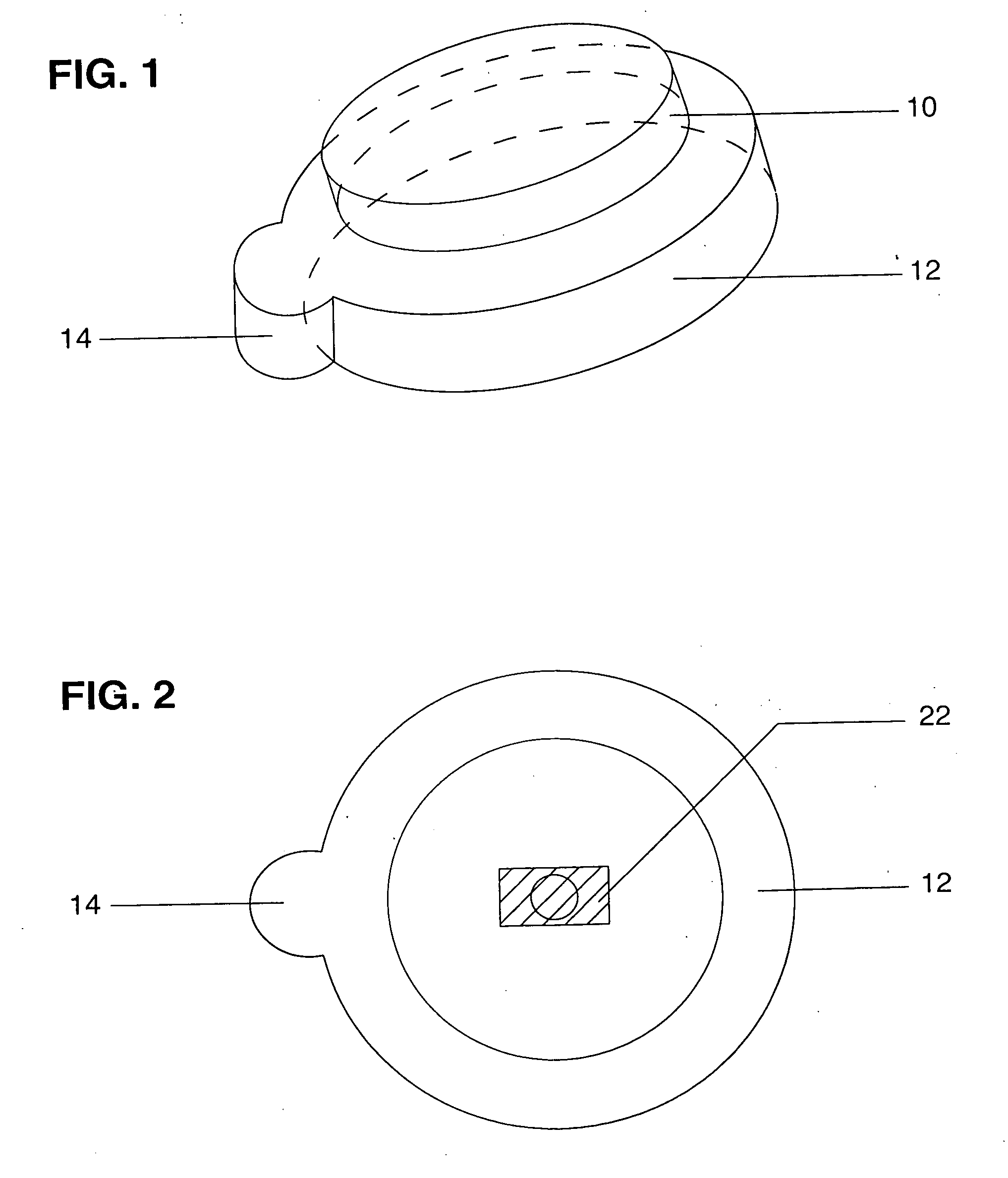
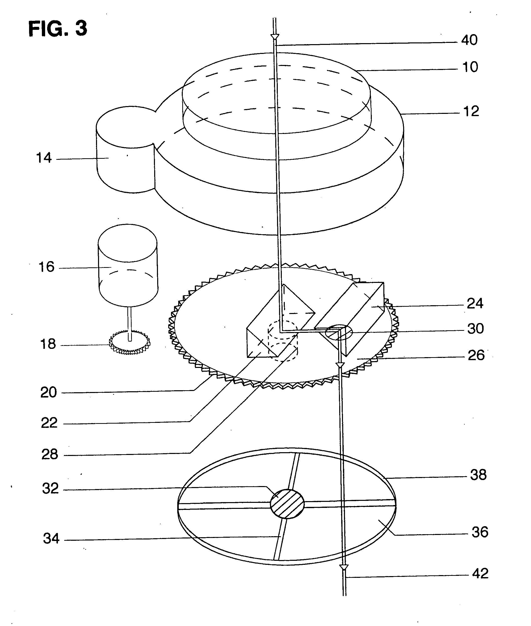
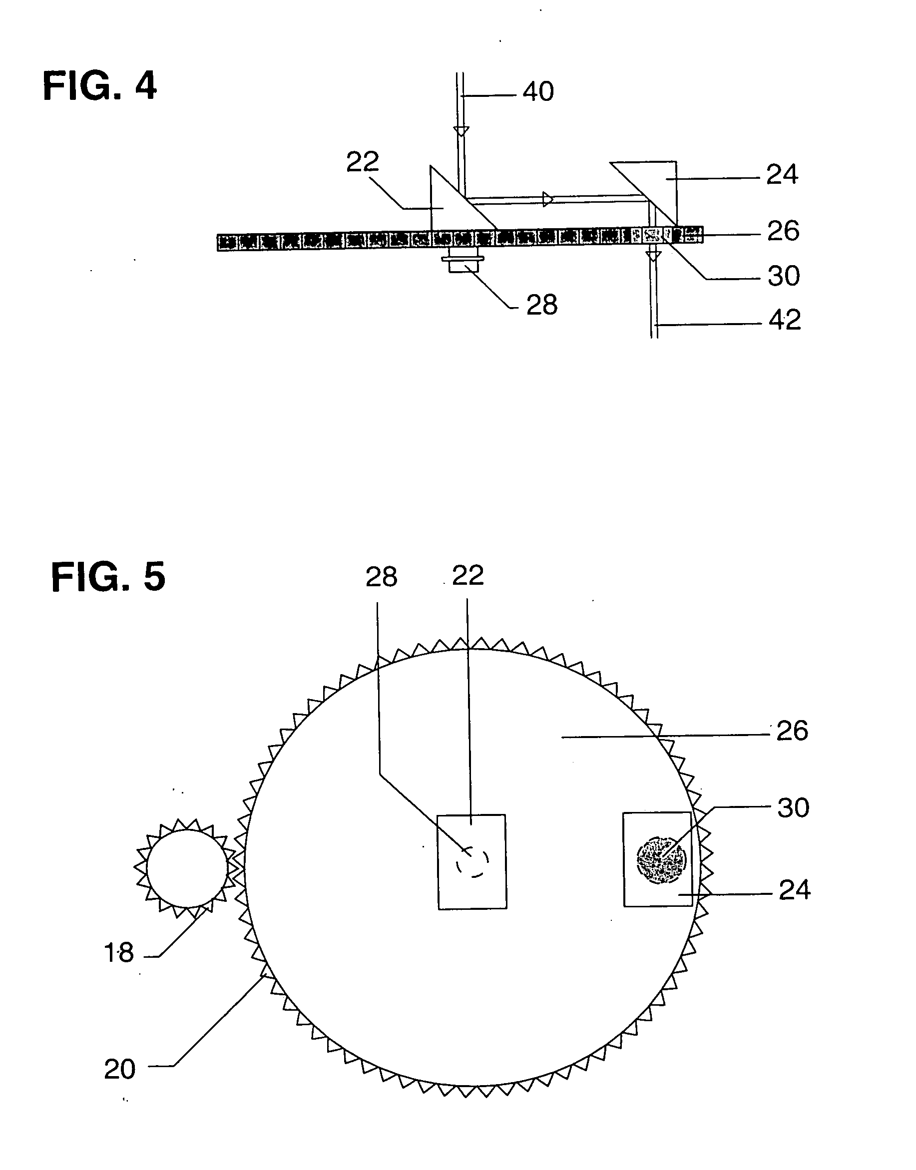
[0060] A preferred embodiment of the invention is shown in FIG. 1-10. The external housing of the laser adaptor is seen in FIG. 1 in a lateral view with the instrument tilted obliquely. Two annular rings are mounted in apposition with the top portion having a smaller diameter. The top ring contains a threaded edge 10 for mounting or screwing into the lens assembly in a laser delivery device. The external casing 12 of the lower ring contains an additional enclosure for the motor casing 14. A top view of the device's configuration is seen in FIG. 2 again showing casing 12 and 14. In addition, a central mirror 22 or prism is mounted internally within the instrument to divert the path of an incoming laser beam. FIG. 3 is an exploded view of the device showing its external and internal construction in detail. Within the casing of the laser instrument adaptor two discs and a micromotor are found. The first and superior plate is a rotary disc 26 that has two...


PUM


Abstract

A beam diverting laser adaptor is disclosed for automating panretinal photocoagulation (PRP). Particularly for use in ophthalmology and laser surgery the apparatus consists of an external casing (12) which is interposed in the laser pathway of a delivery system. Internally, a mobile disc (26) with edge gearing (20) is mounted with mirrors (22) (24) to deflect an incident beam. In close approximation to the rotary disc lies a stationary fenestrated bottom plate (36) for support. A micromotor (16) and shaft gearing (18) coupled to the device spin the top plate. Repetitive laser bursts are timed with the circumferential motion of the mobile plate by a cable (50) and a control box (52). This results in a ring of laser shots and permits a labor intensive treatment to be performed with greater speed, greater efficiency, and greater accuracy.

Description

CROSS-REFERENCE TO RELATED APPLICATIONS [0001] This application is related to application U.S. Ser. No. 11 / 024,308, Filed 2004 Dec. 28 by one of the present inventors. FEDERALLY SPONSORED RESEARCH [0002] Not Applicable SEQUENCE LISTING OR PROGRAM [0003] Not ApplicableBACKGROUND OF THE INVENTION [0004] 1. Field Of The Invention [0005] The present invention relates to ophthalmic devices which facilitate the therapeutic delivery of laser energy to the interior of the eye. [0006] 2. Prior Art [0007] Diabetes Mellitus is a significant health problem. Epidemiologists have estimated that over 17,000,000 Americans now have the disease and statistical models show that by the year 2025 approximately 25,000,000 will suffer from the disorder. On a worldwide basis 120,000,000 people are afflicted with the disease. While the disease has a number of medical complications that often increase with the duration of the illness few are as feared as diabetic retinopathy. In fact, this pathology is the m...

Claims


Application Information

Patent Timeline
Patent Type & Authority Applications(United States)
IPC IPC(8): A61H33/00
CPCA61F9/008A61F9/00821A61F2009/00891A61F2009/00863A61F2009/00872A61F9/00823
Inventor EISENBERG, ELLIOT S.PARTONO, TONY
Owner EISENBERG ELLIOT S
Why Eureka
Try Eureka