
Valve testing device having integrated purge circuit and method of valve testing

a technology of purge circuit and valve testing device, which is applied in the direction of fluid tightness measurement, liquid/fluent solid measurement, instruments, etc., can solve the problems of inoperable valves, one or more pieces of debris may be lodged on the spool, and the valve may experience operational problems, so as to improve the ability of users to process valves and rebuild transmissions. , to achieve the effect of quick and efficient testing, reliable determination of whether a valve is fit for reus

Inactive Publication Date: 2007-02-08
HONDA MOTOR CO LTD
View PDF20 Cites 7 Cited by
  • Summary
  • Abstract
  • Description
  • Claims
  • Application Information

AI Technical Summary

Benefits of technology

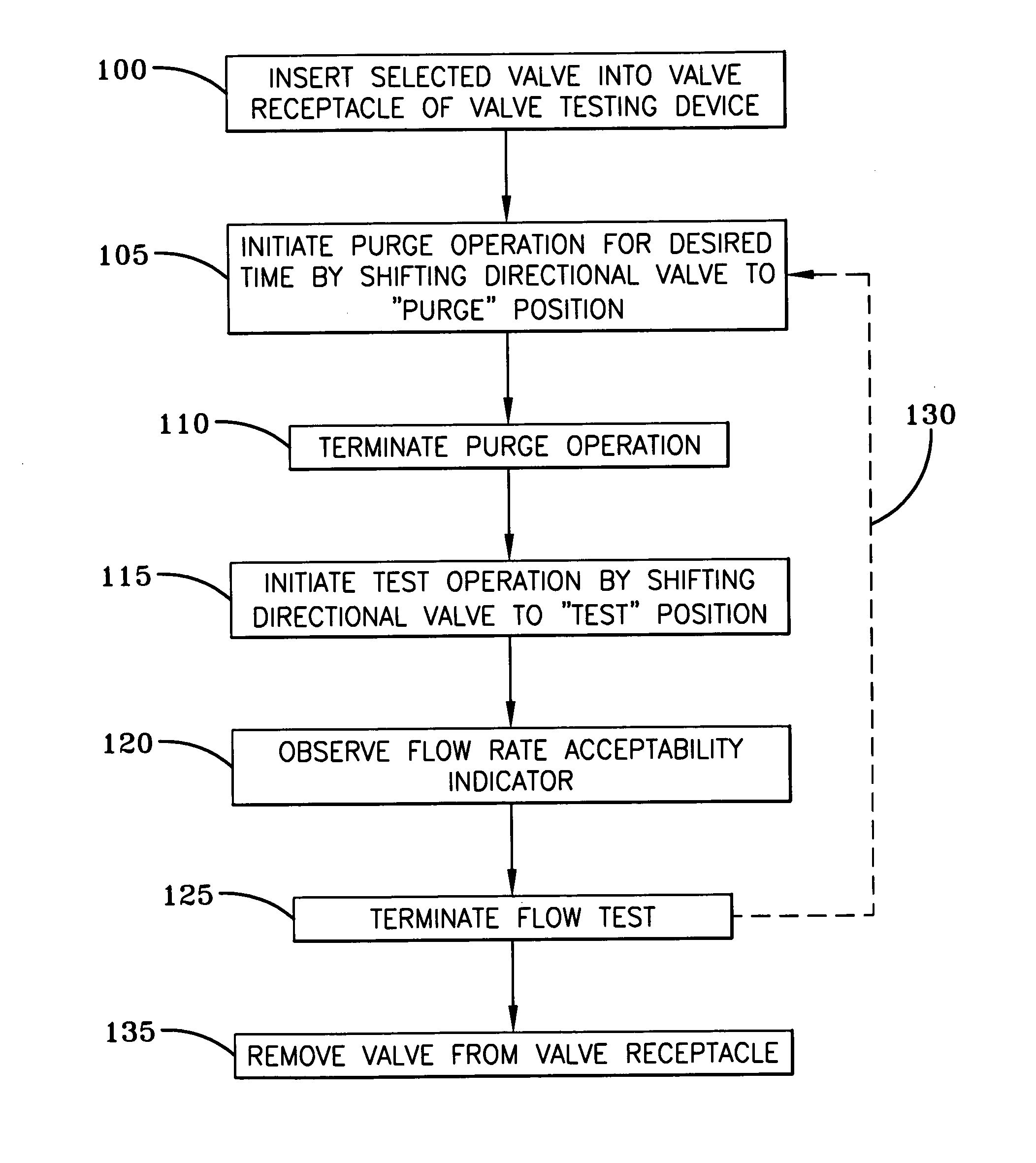
[0010] The valve testing device of the present invention and its method of use allows valves such as those described above to be easily and reliably tested after removal from a vehicle transmission. The device is designed to receive and retain a valve during testing. The device causes fluid to flow through the valve being tested in the same direction that working fluid would normally pass therethrough when the valve is installed to a transmission. The device includes a flow meter or other measuring equipment suitable to determine the flow rate of the fluid as it travels through the valve. By comparing the measured flow rate to an expected flow rate, it can be determined whether the valve is operating acceptably and, hence, can be reused.
[0011] Because it is possible for a valve to exhibit an unacceptable flow rate due to both contamination and more serious defects, the present invention is designed to dislodge contaminants that may reside within the valve. To this end, the device has the ability to also pass fluid through the valve in a direction opposite to the direction that working fluid would normally pass therethrough when the valve is installed to a transmission. This reverse flow of fluid is generally sufficient to dislodge any contaminants of sufficient size to adversely affect the fluid flow through the valve. Use of a reverse fluid flow may be employed only when a valve exhibits an initially unacceptable flow rate. Alternatively, passage of a reverse fluid flow through the valve may be caused to occur before initial testing of the valve in order to help assure that an unacceptable flow rate reading is not due simply to contamination. Therefore, by employing the device and method of the present invention, a user thereof can be reasonably assured that a valve that exhibits an unacceptable flow rate is not just dirty but, rather, is suffering from a defect that renders it unfit for further use.
[0012] The device and method of the present invention allows a user thereof to quickly and efficiently test a large number of such valves. The user is able to reliably determine whether a valve is fit for reuse without having to perform a detailed, and often destructive, inspection of each valve that exhibits a less than acceptable flow rate. Consequently, the device and method of the present invention greatly improves a user's ability to process valves and to rebuild transmissions.

Problems solved by technology

Such a valve may experience operational problems, or may become inoperable, for a number of reasons.
When traveling through a valve, one or more pieces of debris may become lodged on the spool or in the chamber within which the spool moves.
If the piece of debris is of significant size, or a sufficient quantity of debris accumulates, movement of the valve spool and operation of the valve can be negatively affected.
Such a deformation of the valve spool can also cause a malfunction of the valve and negatively affect its ability to regulate fluid flow through the transmission.
An automatic transmission as a whole may malfunction or fail for a number of reasons, not all of which are related to the fluid control valves located therein.
Further, an automatic transmission malfunction or failure may be due to a problem with one or more of its fluid control valves, while a remainder of such valves may be operating normally.
Because of the significant cost involved with replacing an automatic transmission, malfunctioning or failed transmissions are often rebuilt or remanufactured.
Currently known devices and methods do not satisfy these requirements.
The aforementioned devices designed to test valves while they are still installed to a transmission are not readily usable in this setting.
Further, such valves can perform improperly for a number of reasons: some of which can render the valve unusable and some of which may be easily corrected.
For example, a valve may exhibit unacceptable flow characteristics due to the presence of minor contamination, or due to a more serious problem—such as a deformation of a valve stem or spool.
Currently known devices and methods for testing valves cannot readily distinguish between such problems, thereby resulting in the unnecessary disposal of useable valves.

Method used


Image

  • Valve testing device having integrated purge circuit and method of valve testing
  • Valve testing device having integrated purge circuit and method of valve testing
  • Valve testing device having integrated purge circuit and method of valve testing

Examples


Embodiment Construction

)

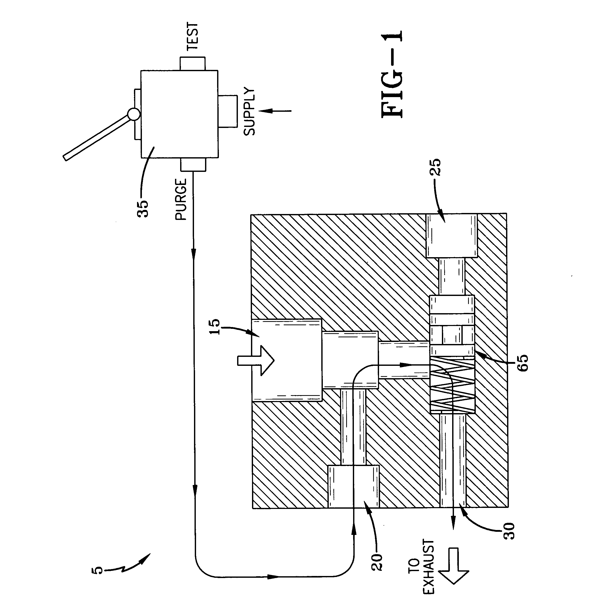
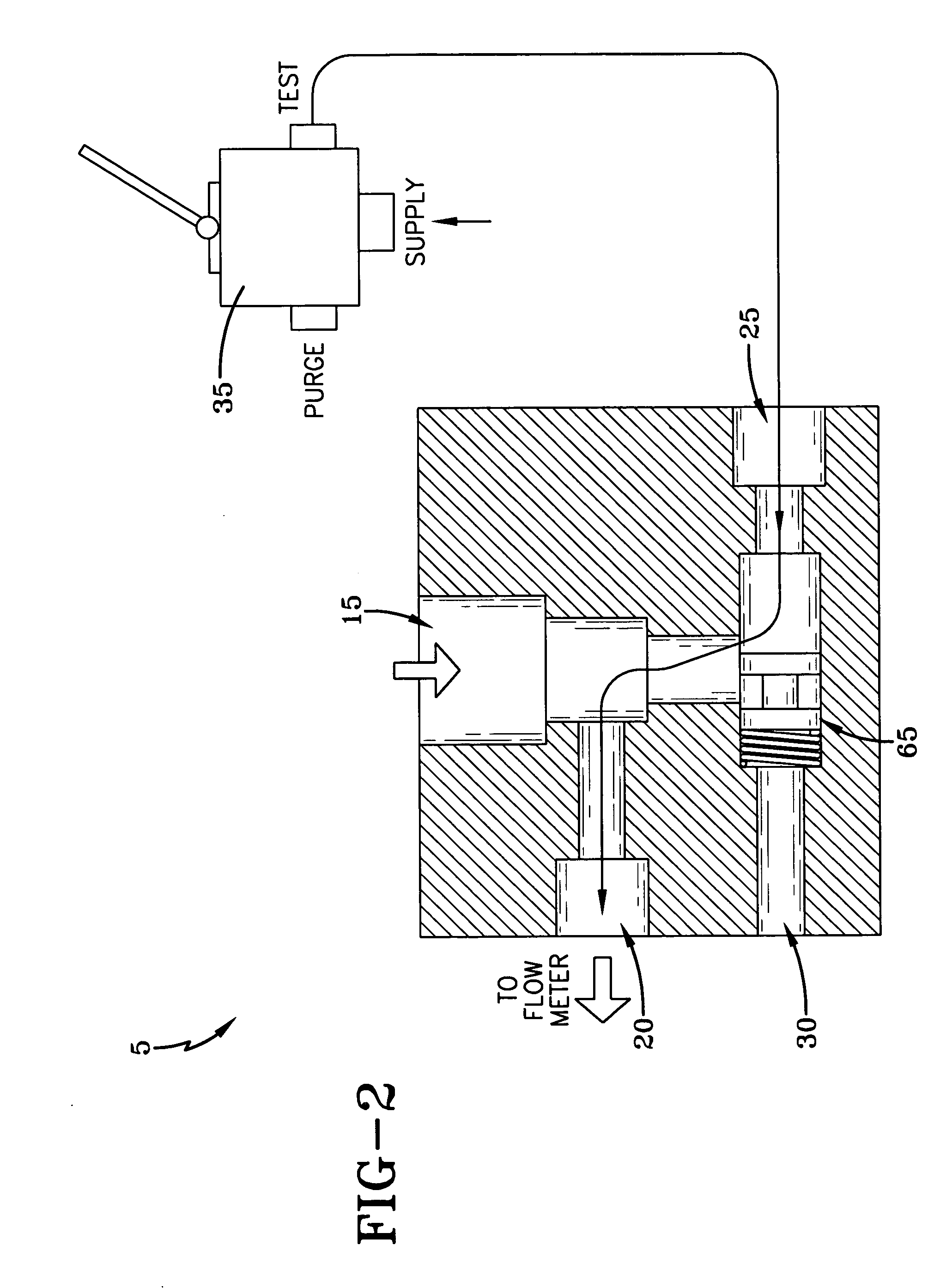
[0020] An exemplary embodiment of a valve testing device 5 of the present invention is represented by the schematic diagram of FIGS. 1-2. The actual testing device 5 may take on many forms, such as a form similar to the portable unit shown in U.S. Pat. No. 6,038,918, for example. The testing device 5 may also be more simplistic in its design and construction, and may or may not be transportable. For example, in contrast to the device shown in U.S. Pat. No. 6,038,918, a testing device of the present invention may be securely mounted to a workbench or other test stand where valve testing is to take place.

[0021] In any event, a valve 10 (see FIG. 3) is preferably received and retained in a valve receptacle 15 of the testing device 5 during testing. The valve receptacle 15 may be a bore of proper size and shape to receive the valve, and may be placed in a block of metal, plastic, or some other material, for example. A purge port 20, a test port 25 and an exhaust port 30 are all shown ...


PUM


Abstract

A valve testing device and method for determining whether a fluid control valve, such as an automatic transmission valve, is operating acceptably. The device and method of the present invention passes pressurized fluid through the valve and to a flow measuring means where the flow rate of fluid through the valve can be measured. Because contamination within such a valve can contribute to unacceptable flow rate measurements, the device and method of the present invention can also pass purge fluid through the valve in a direction that is opposite to the normal flow of working fluid through the valve.

Description

BACKGROUND OF THE INVENTION [0001] The present invention is directed to a device and method for testing the condition of fluid control devices, particularly fluid control valves found in automatic transmissions of vehicles. More particularly, the present invention is directed to a device and method for determining whether such a fluid control device exhibits an acceptable flow rate. [0002] Modern automatic transmissions commonly employ a plurality of fluid control valves in their design and construction. Such valves may take the form of, for example, shift solenoids, pressure regulating solenoids, and pressure switches. [0003] These valves may be of various design, but typically operate to regulate or restrict the passage of fluid through a portion of the automatic transmission. For example, a valve may include a housing containing a solenoid or similar actuating device that is coupled to a movable valve spool. The valve spool moves within a chamber in the housing and acts to regula...

Claims


Application Information

Patent Timeline
Patent Type & Authority Applications(United States)
IPC IPC(8): F16K37/00G01F25/00G01M99/00
CPCF15B19/005F16H2061/0068F16K37/0091
Inventor BAIRD, MICHAELBRIDENSTINE, JAREDCROMES, MICHAEL
Owner HONDA MOTOR CO LTD
Learn More