
Machine for the production of tissue paper

a tissue paper and machine technology, applied in the field of paper making machines, can solve the problems of replacing the poor transfer properties of the tissue paper web from the mesh, and the replacement of the expensive shoe press unit, etc., to achieve good dewatering of the tissue paper web, good gas flow, and good dry content and voluminosity of the tissue paper

Inactive Publication Date: 2007-02-08
VOITH PATENT GMBH
View PDF25 Cites 21 Cited by
  • Summary
  • Abstract
  • Description
  • Claims
  • Application Information

AI Technical Summary

Benefits of technology

[0012] Thanks to the present invention a machine is provided with which it is possible, depending on the skin selected, to produce either high-quality voluminous tissue paper or less high-quality and less voluminous tissue paper. When using the 3-dimensionally structured and permeable skin, in particular the structured mesh, the tissue paper web is formed and dewatered on the structured mesh, as the result of which the tissue paper web acquires in some areas a voluminous structure with a high gsm substance. Thanks to the use of a press roller with bores for the nip formed with the drying cylinder, in particular a Yankee cylinder, a good transfer of the tissue paper web from the structured mesh to the drying cylinder is assured.
[0045] To be able to obtain a good dewatering of the tissue paper web by the mechanical tensioning of the press belt and as the result of the gas flow through the press belt the press belt has an open area of at least 25% and a contact area of at least 10% of its total area facing the upper skin. A uniform mechanical pressure is exerted on the arrangement of the structured upper skin and lower skin by increasing the contact area of the press belt.

Problems solved by technology

In tests, however, rollers with a solid circumferential surface display poor transfer properties of the tissue paper web from the mesh to the Yankee drying cylinder because a vacuum is generated in the opening nip and leads to the tissue paper web adhering to the mesh.
A satisfactory transfer performance is obtained by way of bores in the cylindrical surface of the roller, but the roller casings, known from the prior art with their relatively large bores of more than 3.8 mm, leave unacceptable shadow marks on high-quality tissue paper.
With this method, too, there is a need, due to pressure from costs, to replace the expensive shoe press unit with a cheaper press roller.
However, tests in this connection have shown that rollers with a solid circumferential surface and rollers with blind bores are not suitable for replacing the shoe press unit due to too low a dewatering performance.
Furthermore, manufacturers of tissue paper face changing requirements with regard to the quality and quantity of the tissue paper to be produced.
The provision of production machines for both methods is costly for the tissue paper manufacturer as this means on the one hand that both types of production machines have to be purchased and on the other hand that depending on the current market demands the one or other machine cannot be used for production.

Method used


Image

  • Machine for the production of tissue paper
  • Machine for the production of tissue paper
  • Machine for the production of tissue paper

Examples


Embodiment Construction

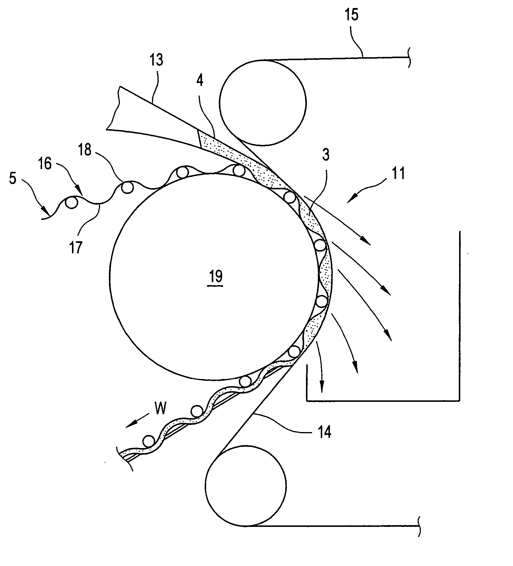
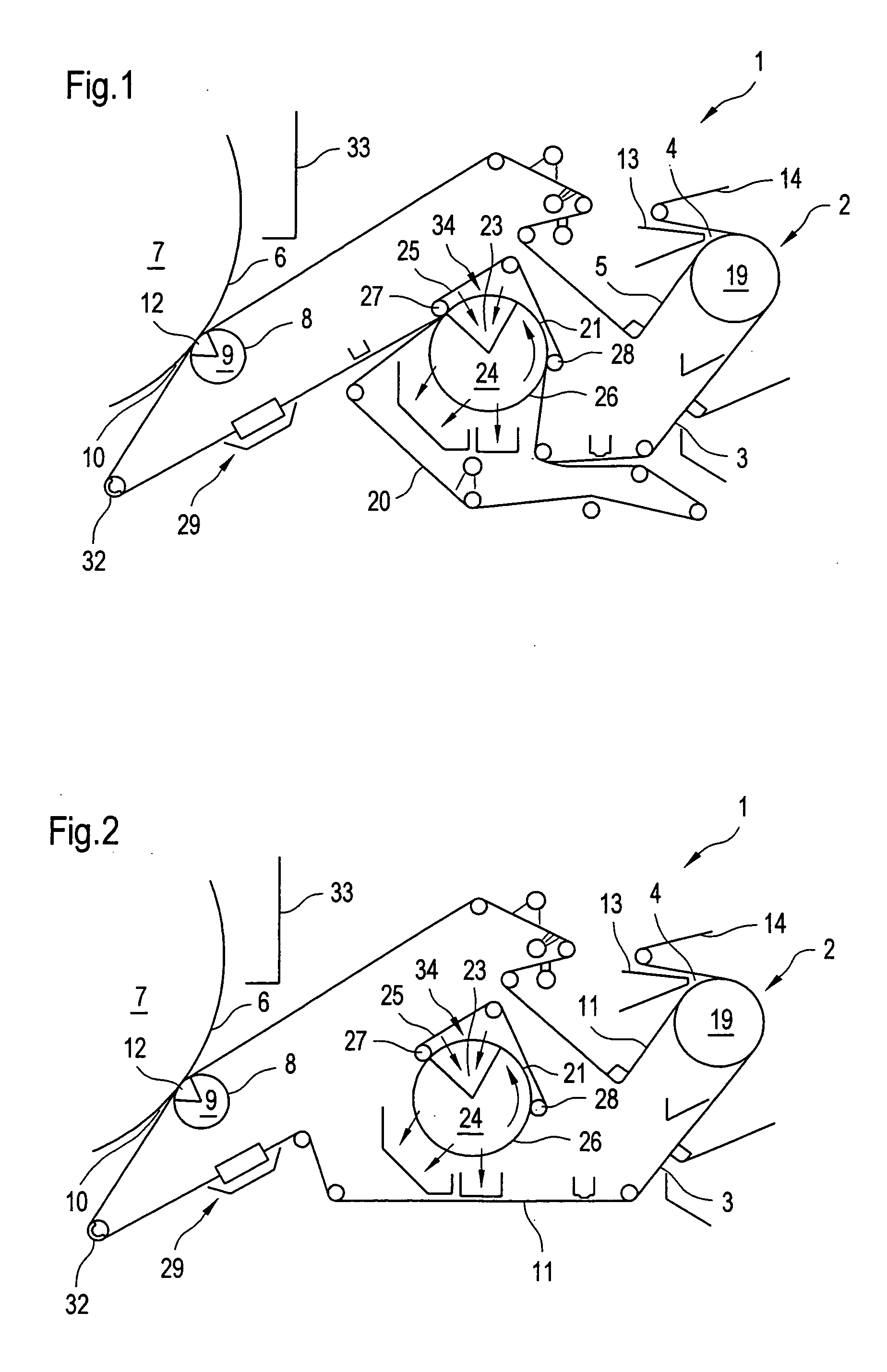
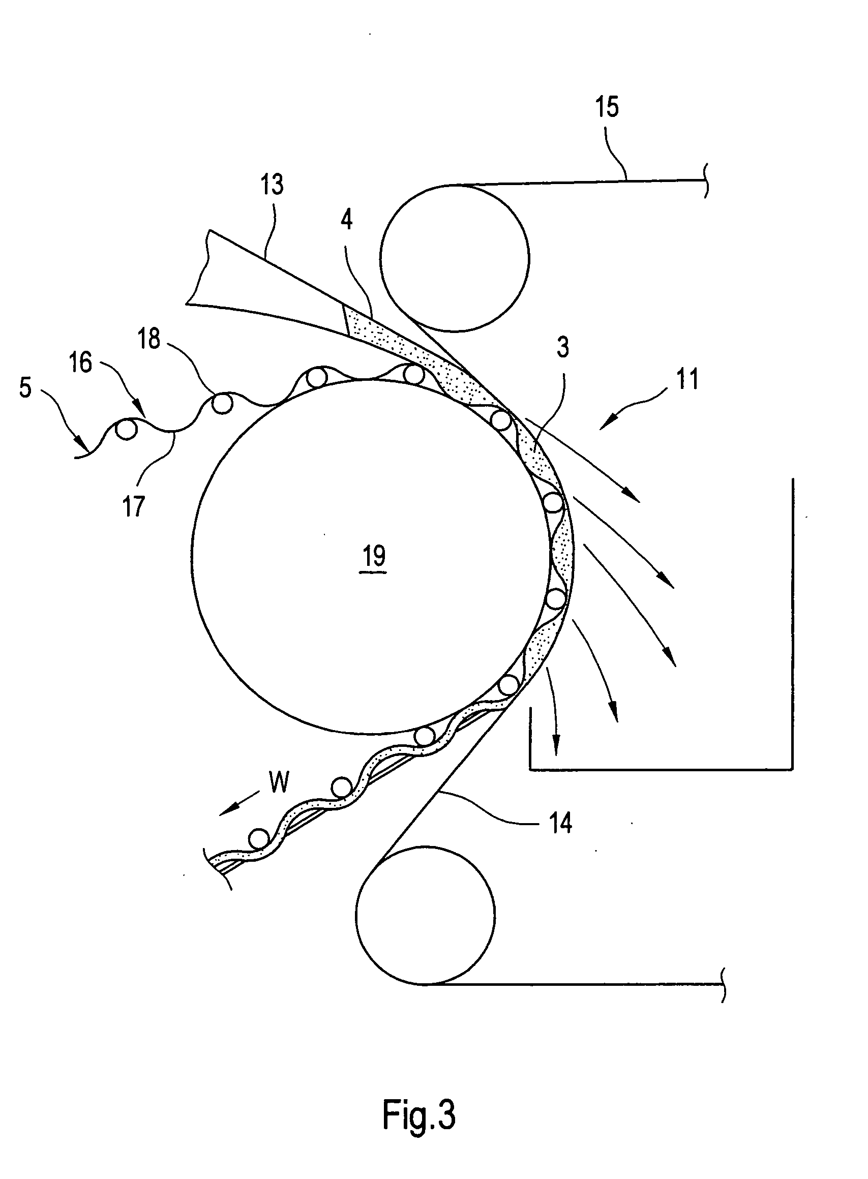
[0058] Referring now to the drawings, and more particularly to FIG. 1 there is shown a tissue paper machine 1 with a forming section 2 in which a tissue paper web 3 is formed from a pulp suspension 4 on a skin 5 (or 11 of FIG. 2) and with a nip 10 that is formed between cylindrical surface 6 of a Yankee drying cylinder 7 and cylindrical surface 8 of a press roller 9 and through which tissue paper web 3 can be conveyed together with skin 5 or 11. According to the present invention the configuration of machine 1 is variable, such that depending on the quality of tissue paper 3 to be produced, for example its absorbency or tear resistance, either a structured mesh 5 or a felt 11 (this configuration is shown in FIG. 2) is used. Press roller 9 includes a suction zone 12 and bores 30 communicating with suction zone 12 which are provided in the cylindrical surface 8 of the press roller 9.

[0059] In the configurations presented in the FIGS. 1 and 2 structured mesh 5 is used for the producti...


PUM


Abstract

This invention relates to a machine for the production of a tissue paper web with a forming section in which the tissue paper web is formed from a pulp suspension on a skin and with a nip which is formed between the cylindrical surface of a drying cylinder, in particular a Yankee drying cylinder, and a mating surface and through which the tissue paper web can be conveyed together with the skin. The configuration of the machine is variable such that, depending on the quality of the tissue paper to be produced, for example its absorbency or tear resistance, the skin is either a three-dimensionally structured skin, a structured mesh, a non-structured skin, or a felt, whereby the mating surface is formed by the cylindrical surface of a press roller which includes a suction zone and in which provision is made for bores communicating with the suction zone.

Description

BACKGROUND OF THE INVENTION [0001] 1. Field of the Invention [0002] The present invention relates to a paper making machine, and, more particularly, to a machine for the production of tissue paper. [0003] 2. Description of the Related Art [0004] Many different types of production processes for tissue paper are known. [0005] The expensive TAD method or the method described in PCT / EP2005 / 050203, for example, are used for the production of a particularly high-quality and fleecy tissue paper with a higher absorbency and high water absorption capacity coupled with high tear resistance. With the method described in PCT / EP2005 / 050203 the tissue paper web is formed in the forming section on a structured mesh and then dewatered in several dewatering steps under the action of pressure. For example, the tissue paper web is conveyed throughout the dewatering on the structured mesh on which it was formed. In this way a tissue paper with voluminous, less compressed areas, and with compressed soli...

Claims


Application Information

Patent Timeline
Patent Type & Authority Applications(United States)
IPC IPC(8): D21F9/00
CPCD21F3/0209D21F3/0272D21F11/145D21F3/10D21F11/14D21F3/0281
Inventor SCHERB, THOMASSILVA, LUIZ CARLOSBERARDI, ROGERIOOYAKAWA, DANILO
Owner VOITH PATENT GMBH
Learn More