Cooling system for vehicle alternator

a technology for vehicle alternators and cooling systems, which is applied in the direction of electrical equipment, dynamo-electric machines, electrical components, etc., can solve the problems of reducing the life of electric components and mechanical components forming the alternator, reducing the output power of the alternator, and reducing the cooling capacity. , to achieve the effect of enhancing the cooling capacity, preventing accumulation of foreign matter, and improving the cooling capacity

Inactive Publication Date: 2007-02-08
DENSO CORP
View PDF13 Cites 6 Cited by
  • Summary
  • Abstract
  • Description
  • Claims
  • Application Information

AI Technical Summary

Benefits of technology

[0008] It is an object of the present invention to provide a cooling system for a vehicle alternator having an improved cooling capability and capable of preventing accumulation of foreign matters such as muddy water and sand, splashed from a muddy road, on a cooling air inlet window of the alternator.
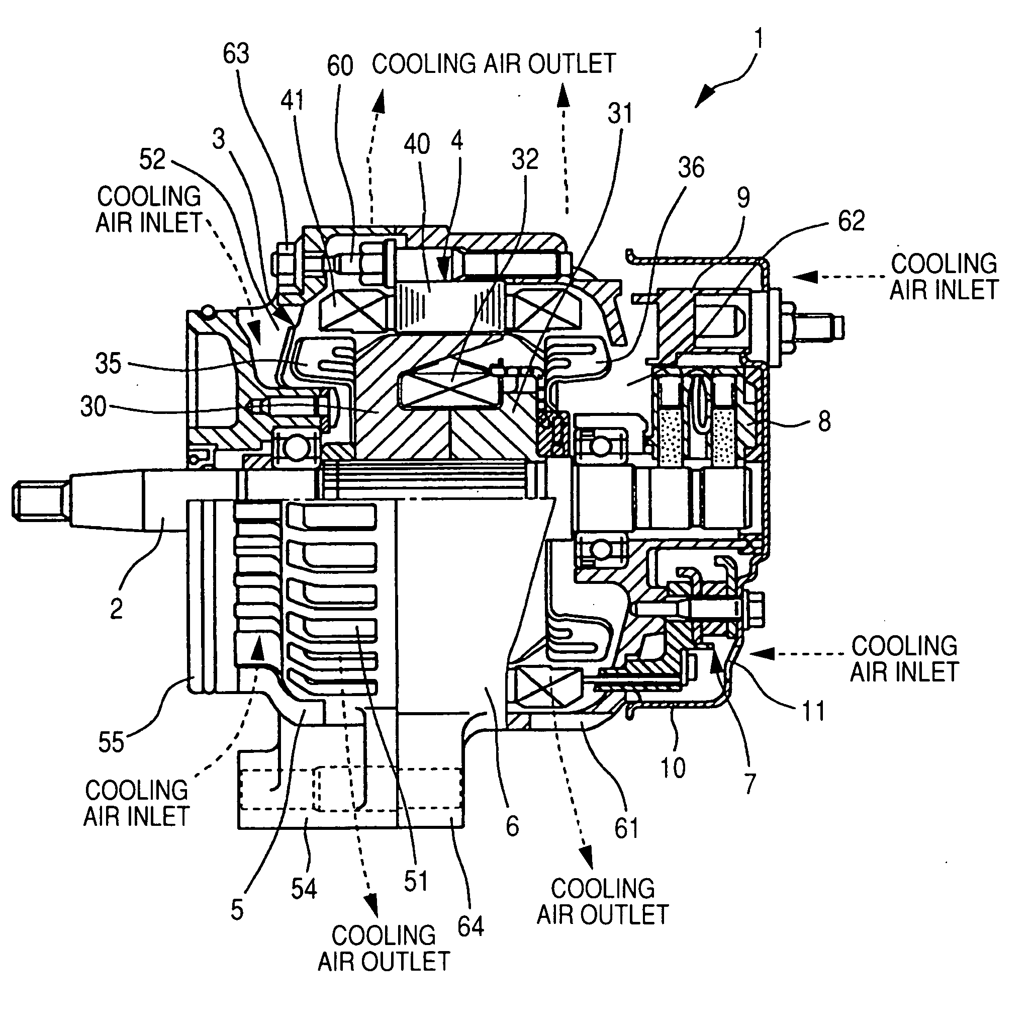
[0009] To achieve the above purposes, the present invention provides a cooling system for an alternator mounted on a vehicle, having a front frame, a rear frame, and a cooling air duct. The front frame is fixed to an engine fixture section side on which an engine is mounted. The front frame is configured to accommodate a rotor of the alternator having cooling fans, and to freely and rotationally support a rotary shaft of the alternator to be driven by the engine directly connected to the rotary shaft. The front frame has a cooling air outlet window and a cooling air inlet window. The cooling air outlet window is formed at an outer peripheral side of a stator coil that is wound on the stator. The stator is placed at an outer peripheral side of the rotor. The cooling air inlet window is formed at the engine fixture section side. The cooling air inlet window is separated from the cooling fans of the rotor along an axis direction of the rotary shaft. The rear frame is configured to accommodate a stator of the alternator. The cooling air duct has an inlet section and an outlet section. The inlet section is configured to introduce a cooling air. The outlet section configured to exhaust the cooling air is placed at the position near the cooling air inlet window of the front frame. Because the outlet section of the cooling air duct is placed at the position near the cooling air inlet window mounted on the front frame, it is thereby possible to introduce a fresh cooling air into the cooling air inlet window and to enhance the cooling capability for the alternator mounted on a vehicle such as a motor bicycle.
[0010] Further, according to another aspect of the present invention, the inlet section of the cooling air duct is placed in the running direction of the vehicle so that the cooling air is introduced into the inlet section of the cooling air duct in the running direction of the vehicle, and then exhausted from the outlet section of the cooling air duct in the backward direction to the running of the vehicle. It is thereby possible to efficiently introduce the cooling air into the cooling air duct and to blow the cooling air to the cooling air inlet window formed in the front frame. As a result, it is possible to blow the cooling air exhausted from the outlet section of the cooling air duct to foreign matters such as muddy water and sand splashed from the ground in the forward direction of running of the vehicle. Thus, it is thereby possible to eliminate any accumulation of muddy water and sand on the cooling air inlet window formed in the front frame.
[0011] Still further, according to another aspect of the present invention, the rotary shaft of the rotor is assembled to the vehicle in parallel to the ground, and the outlet section of the cooling air duct is placed at the position under the rotary shaft of the rotor. Because muddy water and sand splashed from the ground during the running of the vehicle are adhered mainly to the front frame under the position of the rotary shaft, it is possible to efficiently eliminate those muddy water and sand splashed from the ground by the cooling air forcedly exhausted from the outlet section of the cooling air duct placed at the position near the cooling air inlet window under the position of the rotary shaft.
[0012] Still further, according to another aspect of the present invention, the cooling air duct is so placed that the cooling air exhausted from the outlet section of the cooling air duct do not interfere with the cooling air exhausted from the cooling air outlet window. It is thereby possible to further enhance the cooling capability of the cooling system and to prevent decreasing of the flow speed of the cooling air and decreasing of the flow amount of the cooling air even if the cooling air duct is added to the cooling system.
[0013] Furthermore, according to another aspect of the present invention, a sectional area of the inlet section of the cooling air duct is greater than a sectional area of the outlet section of the cooling air duct. Because the blowing speed of the cooling air exhausted from the outlet section of the cooling air duct is thereby accelerated, it is possible to efficiently eliminate muddy water and sand splashed from the ground and also to prevent the accumulation of those foreign matters on the cooling air inlet window and the cooling air outlet window formed in the front frame.

Problems solved by technology

This cooling system of the alternator mounted on such a motor bicycle therefore reduces its cooling capability.
In addition, the deterioration of the cooling capability of the cooling system reduces the lifetime of electric components and also mechanical components forming the alternator, and the output power of the alternator is thereby reduced by increasing the temperature of the stator and the rotor forming the alternator.
Further, because the alternator mounted on the motor bicycle is placed at the outside of the engine and exposed to the outer atmosphere, foreign matters such as muddy water and sand are splashed from the ground and then adhered to the cooling air inlet window formed at a front side of the alternator while the motor bicycle is running on a mud road.
The accumulation of those foreign matters on the cooling air inlet window formed at the front side of the alternator reduces the amount of cooling air to be introduced to the alternator through the cooling window, and further decreases the cooling capability of the cooling system of the alternator.
If those foreign matters such as muddy water and sand are accumulated on and adhered to the cooling air inlet window and then invade to the inside of the alternator, the invasion of the mud and sand to the inside of the alternator has a possibility to stop the operation of the alternator and to decrease the capability of the alternator to generate the electric power.

Method used


Image

  • Cooling system for vehicle alternator
  • Cooling system for vehicle alternator
  • Cooling system for vehicle alternator

Examples


embodiment

[0023] A description will be given of the configuration of the cooling system for a vehicle alternator according to the first embodiment of the present invention with reference to diagrams.

[0024]FIG. 1 is a sectional view showing an entire configuration of the vehicle alternator equipped with the cooling system to be mounted on a motor bicycle as a vehicle according to the first embodiment of the present invention. FIG. 2 is a plan view of the alternator equipped with the cooling system and FIG. 3 is a rear view of the alternator equipped with the cooling system.

[0025] As shown in FIG. 1, the vehicle alternator 1 (or referred to as “an alternator”, simply) has a rotary shaft 2, a rotor 3, a stator 4, a front frame 5, a rear frame 6, a rectifier unit 7, a brush unit 8, a regulator 9 as a voltage control unit, and the like. A front part of the rotary shaft 2 is engaged with a gear 102 as an engine side driving component placed in the engine block 100 in order to receive the output p...


PUM


Abstract

A front frame for an alternator mounted on a motor bicycle has a cooling air outlet window formed at an outer peripheral side of a stator coil wound on a stator and a cooling air inlet window formed at a front side of the alternator, namely, at an engine block side along an axis direction separated from a cooling fan. An outlet section of a cooling air duct is placed at a position near the cooling air inlet window. This configuration of the cooling system enhances its cooling capability of forcedly blowing the cooling air to the inside of the alternator, and prevents adhesion and accumulation of mud and sand to the cooling air inlet window, splashed to the cooling air inlet window while the motor bicycle is driving on a mud road.

Description

CROSS-REFERENCE TO RELATED APPLICATIONS [0001] This application is related to and claims priority from Japanese Patent Application No. 2005-226066 filed on Aug. 4, 2005, the contents of which are hereby incorporated by reference. BACKGROUND OF THE INVENTION [0002] 1. Field of the invention [0003] The present invention generally relates to a cooling system for a vehicle alternator to be mounted on a vehicle such as a motor bicycle. [0004] 2. Description of the Related Art [0005] In general, a vehicle alternator (or referred to as “an alternator”, simply) mounted on a motor bicycle is exposed to the outer atmosphere. Such an alternator for a motor bicycle is directly engaged with an engine cover through a shaft, which is different in mechanism from an alternator mounted on a passenger car or a truck in which an alternator is engaged with an engine cover through a pulley and a belt. The Japanese patent laid open publication (No. JP H8-331786) has disclosed such a mechanism of the alter...

Claims


Application Information

Patent Timeline
Patent Type & Authority Applications(United States)
IPC IPC(8): H02K9/00
CPCH02K5/20H02K5/207
Inventor SAKAKIBARA, HIROSHI
Owner DENSO CORP
Why Eureka
Try Eureka