
Measurement tool for obtaining tool face on a rotating drill collar

a technology of measuring tool and drill collar, which is applied in the direction of instruments, borehole/well accessories, surveys, etc., can solve the problems of insufficient communication bandwidth with the surface, inability to centralize or stabilize lwd tools, and inability to meet the needs of typical lwd applications, etc., to achieve advantageously minimize or even substantially eliminate magnetic interference, improve circumferential sensitivity, and reduce the effect of cos

Active Publication Date: 2007-02-08
SCHLUMBERGER TECH CORP
View PDF99 Cites 45 Cited by
  • Summary
  • Abstract
  • Description
  • Claims
  • Application Information

AI Technical Summary

Benefits of technology

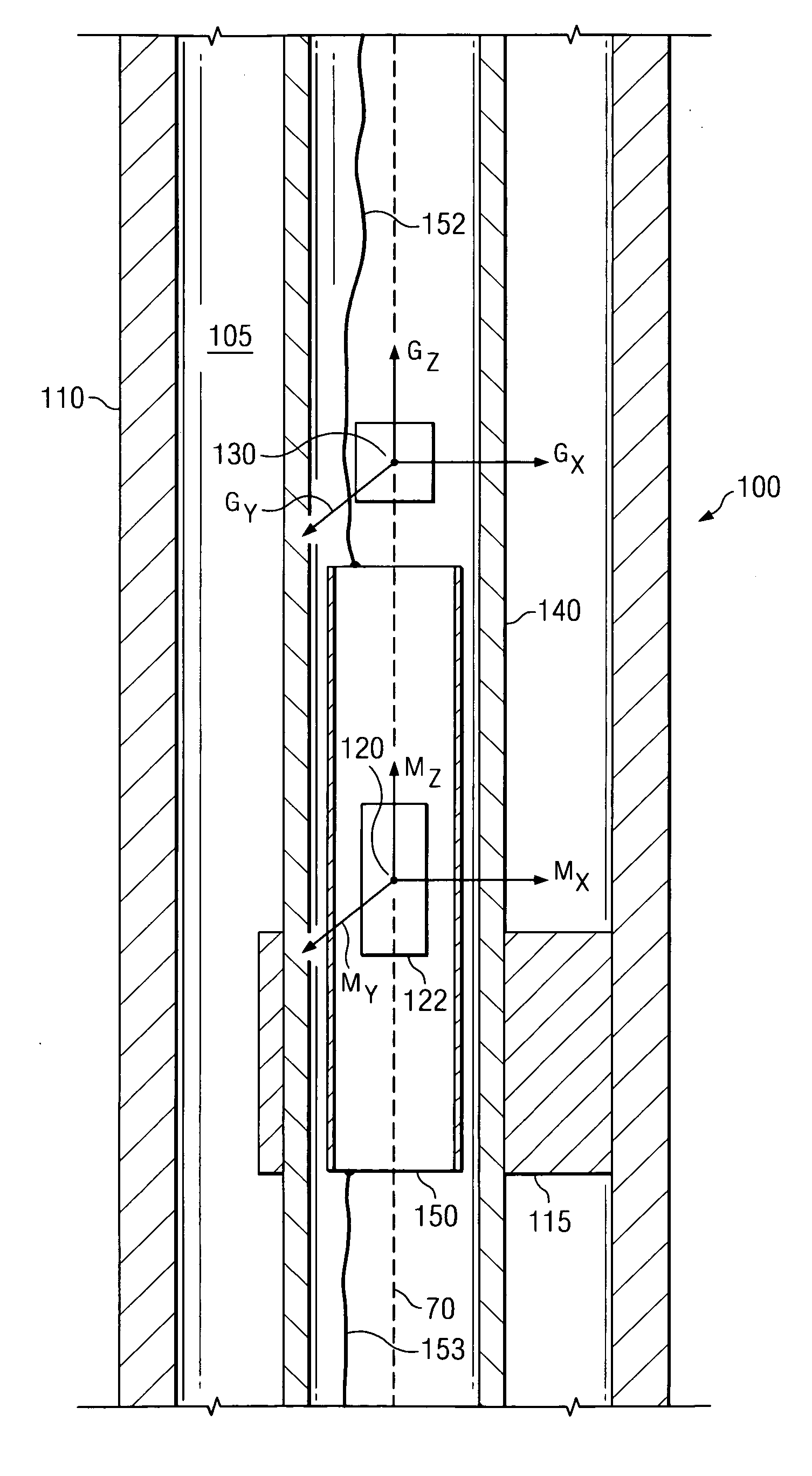
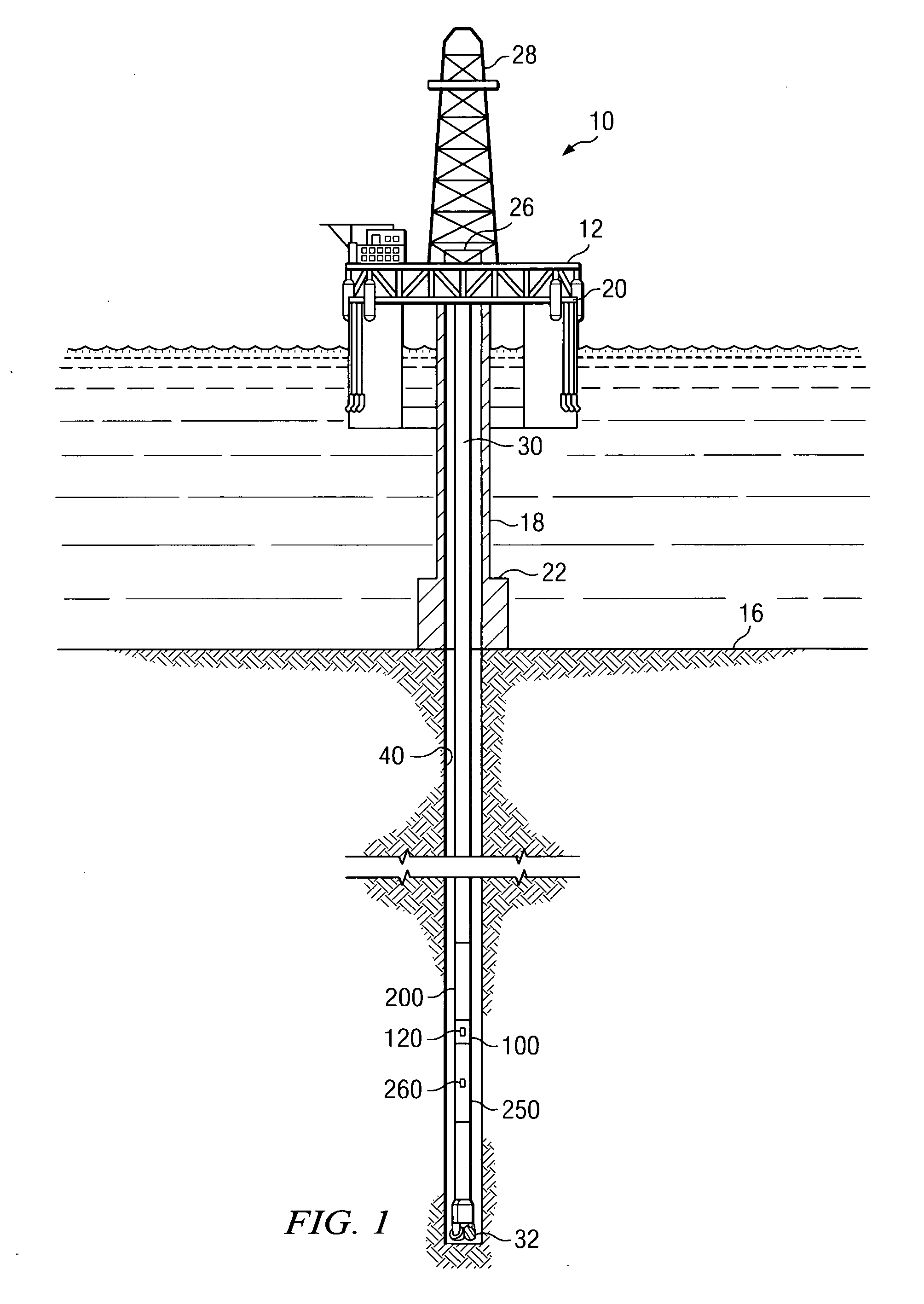
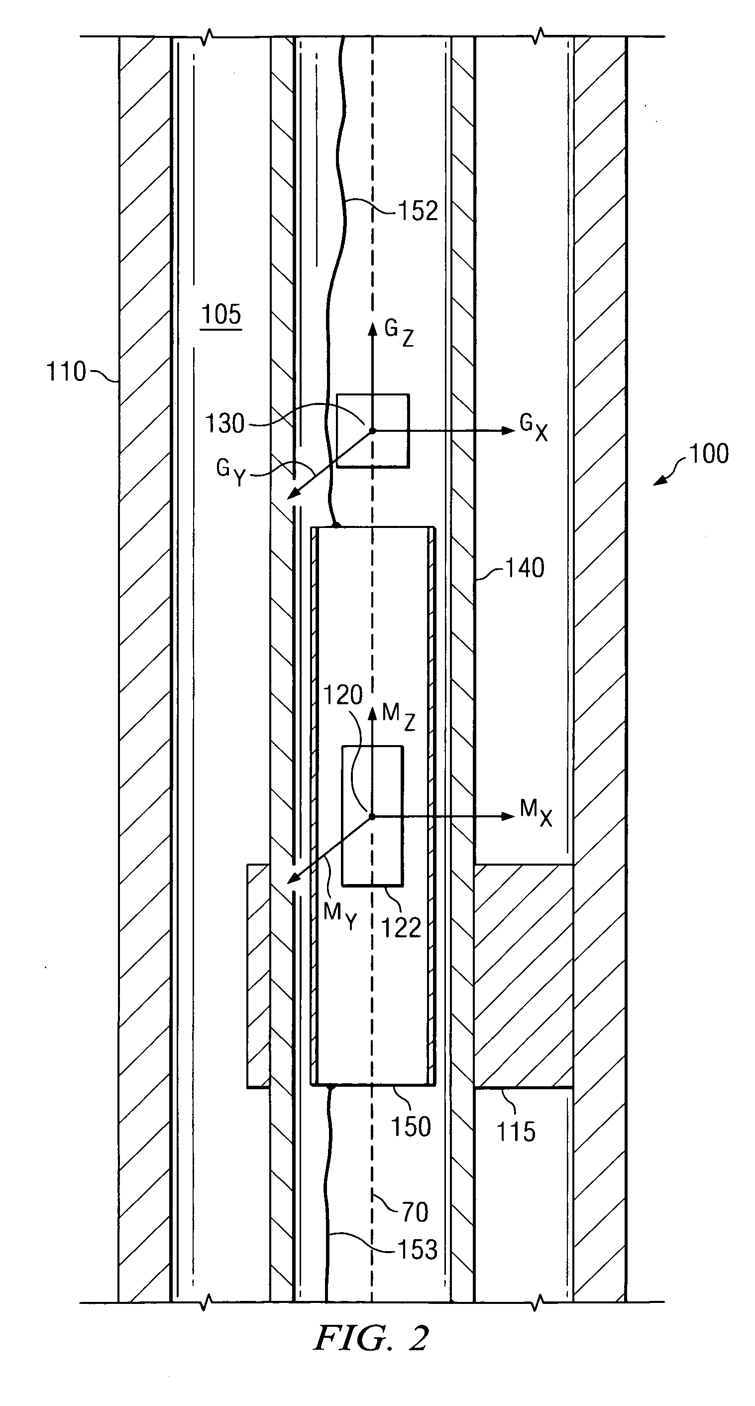
[0009] Exemplary embodiments of the present invention may advantageously provide several technical advantages. For example, embodiments of this invention advantageously enable tool face angles to be measured in substantially real time on a rotating drill collar. As such, embodiments of this invention may be utilized in conjunction with circumferentially sensitive LWD tools to form borehole images having improved circumferential sensitivity. Embodiments of the present invention also provide a less expensive and potentially more rugged means of obtaining real-time tool face angle information. Moreover, in exemplary embodiments of this invention, the magnetic field sensors are deployed to advantageously minimize or even substantially eliminate magnetic interference due to the transmission of electrical power through the tool, thereby improving the accuracy of the calculated tool face angles.

Problems solved by technology

It will be appreciated by those of ordinary skill in the art that such wireline arrangements are not suitable for typical LWD applications.
In particular, communication bandwidth with the surface would typically be insufficient during LWD operations (e.g., via known telemetry techniques) to carry large amounts of image-related data.
Further, LWD tools are generally not centralized or stabilized during operation and thus require more rugged sensor arrangements.
While flux gate magnetometers (also referred to in the art as ring core magnetometers) can be used in borehole surveying applications, such magnetometers have some characteristics that are not ideally suited to imaging applications.
In LWD applications, electrical power is often supplied by batteries, making such power a somewhat scarce resource.
For this reason, increasing the bandwidth of flux gate magnetometers beyond about 5 Hz is not practical in many LWD applications.
Flux gate magnetometers, therefore, are not well suited for making substantially real-time tool face angle measurements in many LWD settings.
Though magnetometers have been used in many LWD and MWD tools, these instruments present design challenges that add to the complexity and expense of the tools.
The magnetometers are also relatively expensive, which further compounds this problem.
The magnetic field about the electrical transmission line is known to interfere with nearby magnetometers.
While AC fields may be filtered in certain applications, DC fields are particularly difficult to accommodate.

Method used


Image

  • Measurement tool for obtaining tool face on a rotating drill collar
  • Measurement tool for obtaining tool face on a rotating drill collar
  • Measurement tool for obtaining tool face on a rotating drill collar

Examples


Embodiment Construction

[0019] Before proceeding with a discussion of the present invention, it is necessary to make clear what is meant by “azimuth” as used herein. The term azimuth has been used in the downhole drilling art in two contexts, with a somewhat different meaning in each context. In a general sense, an azimuth angle is a horizontal angle from a fixed reference position. Mariners performing celestial navigation used the term, and it is this use that apparently forms the basis for the generally understood meaning of the term azimuth. In celestial navigation, a particular celestial object is selected and then a vertical circle, with the mariner at its center, is constructed such that the circle passes through the celestial object. The angular distance from a reference point (usually magnetic north) to the point at which the vertical circle intersects the horizon is the azimuth. As a matter of practice, the azimuth angle was usually measured in the clockwise direction.

[0020] In this traditional m...


PUM


Abstract

An apparatus for obtaining tool face angles on a rotating drill collar in substantially real time is disclosed. In one exemplary embodiment the apparatus includes a magnetoresistive magnetic field sensor deployed in a tool body. The apparatus further includes a programmed processor configured to calculate tool face angles in substantially real time from the magnetic field measurements. The programmed processor may optionally further be configured to correlate the calculated tool face angles with logging while drilling measurements for use in borehole imaging applications.

Description

FIELD OF THE INVENTION [0001] The present invention relates generally to an apparatus for logging a subterranean borehole. More specifically, this invention relates to a measurement tool for making substantially real time tool face angle measurements on a rotating drill collar. By linking such measurements to contemporaneously obtained real time measurements of certain formation properties, the azimuthal variation of the measured property may be determined. In this manner, an image of the measured property within the borehole may be developed. The present invention, therefore, relates specifically to a tool and method for obtaining and processing the real time tool face angle measurements required for borehole imaging applications. BACKGROUND OF THE INVENTION [0002] Wireline and logging while drilling (LWD) tools measure physical properties of the formations through which a borehole traverses. Such logging techniques include, for example, natural gamma ray, spectral density, neutron...

Claims


Application Information

Patent Timeline
IPC IPC(8): G01V3/00
CPCE21B47/024E21B47/022G01V1/40G01V3/18G01V5/04
Inventor MOORE, ROBERT A.
Owner SCHLUMBERGER TECH CORP
Learn More