Optical beam scanning device

a scanning device and optical beam technology, applied in the field of optical beam scanning devices, can solve the problems of large powers that cannot be provided to the lenses themselves, and achieve the effect of suppressing the increase in the length of the optical path, reducing the degree of freedom of shape and arrangemen

Inactive Publication Date: 2007-02-08
KK TOSHIBA +1
View PDF9 Cites 13 Cited by
  • Summary
  • Abstract
  • Description
  • Claims
  • Application Information

AI Technical Summary

Benefits of technology

[0023] An optical beam scanning device includes a rotating polygon mirror for scanning a beam from a pre-deflection optical system in a main scanning direction and two mirrors for imaging the beam scanned by the rotating polygon mirror on an image plane, and a first mirror at the rotating polygon mirror side has a negative power in the main scanning direction and a second mirror at the image plane side has a positive power in the main scanning direction. Thereby, the degrees of freedom of shape and arrangement of process unit or the like can be made higher and the optical beam scanning device, an exposure apparatus and an image forming apparatus incorporating the optical beam scanning device can be downsized by securing the distance between the last imaging element and the image plane while suppressing the increase in the optical path length between the reflection surface of the rotating polygon mirror and the image plane.

Problems solved by technology

Further, there is a device using a pair of plastic lenses as one employing optical elements using inexpensive molded components, and there is a restriction that large powers can not be provided to the lenses themselves in order to suppress the influences of temperature and humidity to the refractive indexes and shapes.

Method used


Image

  • Optical beam scanning device
  • Optical beam scanning device
  • Optical beam scanning device

Examples


first embodiment

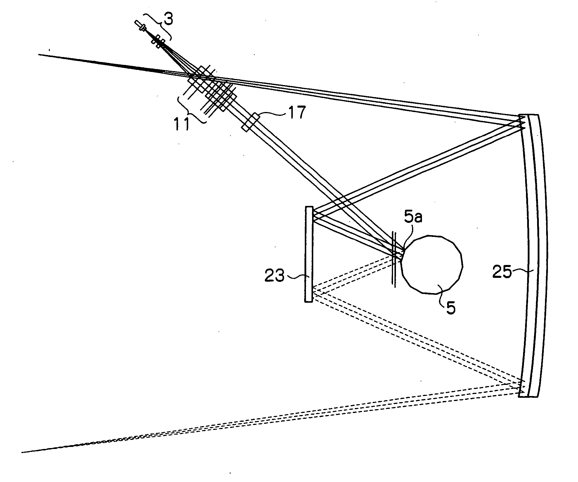
[0042] An exposure apparatus incorporating an optical beam scanning device according to the embodiment includes a rotating polygon mirror for scanning a beam from a pre-deflection optical system in a main scanning direction, and two mirrors (a first mirror at the rotating polygon mirror side and a second mirror at an image plane side) for imaging the beam scanned by the rotating polygon mirror on the image plane. A specific example of the exposure apparatus will be described in detail in a specific example. In the exposure apparatus, the first mirror at the rotating polygon mirror side has a negative power in the main scanning direction and the second mirror at the image plane has a positive power in the main scanning direction. According to the configuration, in the scanning optical system with mirrors, the degrees of freedom of shape and arrangement of process unit or the like can be made higher, and the exposure apparatus and an image forming apparatus incorporating the exposure ...

second embodiment

[0054] An exposure apparatus incorporating an optical beam scanning device according to the embodiment is limited in requirement of each mirror in the sub-scanning direction in addition to the above described first embodiment.

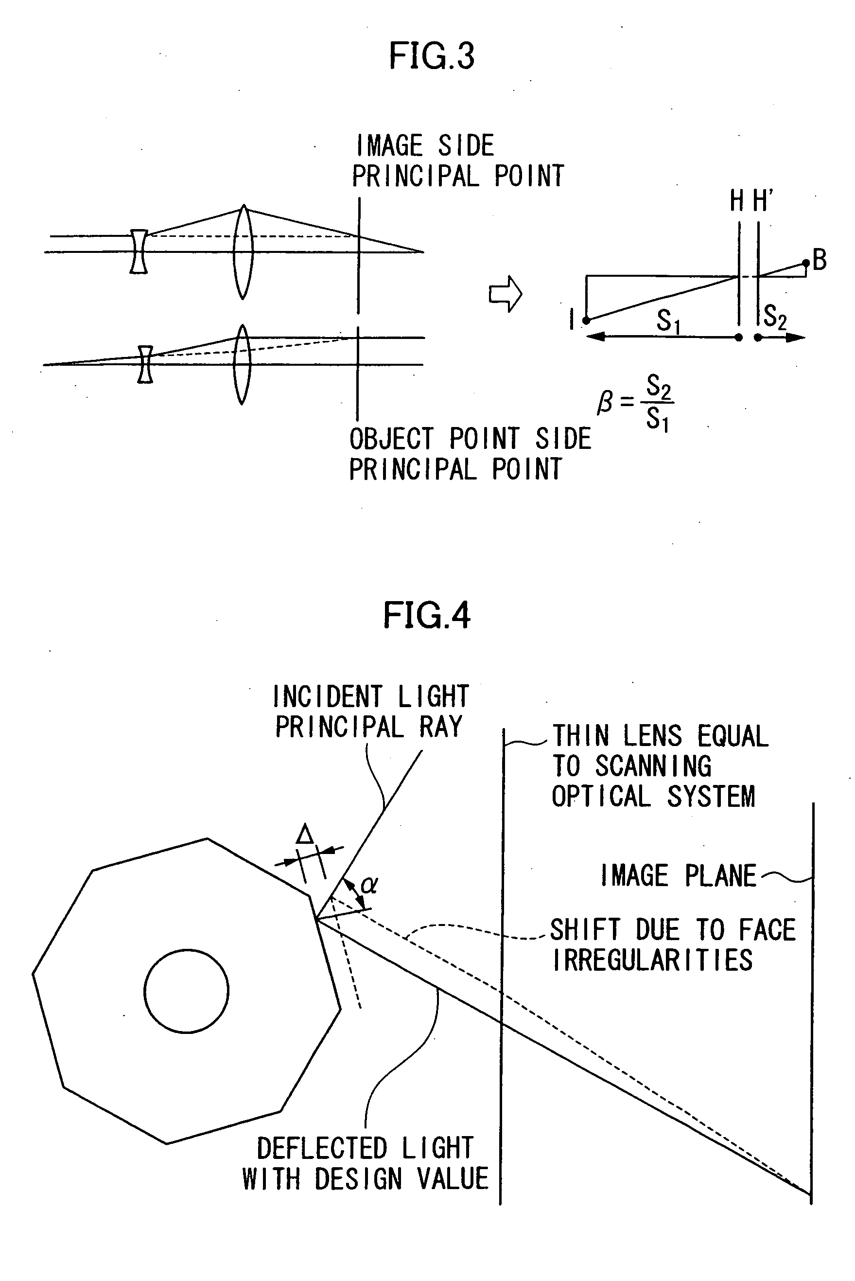
[0055] In the exposure apparatus according to the embodiment, in each mirror of the above described first embodiment, the first mirror is formed to have a negative power in the sub-scanning direction and the second mirror is formed to have a positive power in the sub-scanning direction, and the image plane side principal point is located nearer the image plane than the second mirror both in the main scanning direction and the sub-scanning direction.

[0056] When a beam is diagonally entered into the rotating polygon mirror, including both cases of design and manufacturing tolerance, the influence by the face irregularities of the rotating polygon mirror appears as displacement of scanning lines in the sub-scanning direction. With respect to the sub-scanning dir...

third embodiment

[0059] An exposure apparatus incorporating an optical beam scanning device according to the embodiment is further limited in requirement of each mirror in the sub-scanning direction in the above described second embodiment.

[0060] In the exposure apparatus according to the embodiment, in each mirror of the above described second embodiment, the absolute value of the sub-scanning direction power of the first mirror is set larger than the absolute value of the sub-scanning direction power of the second mirror.

[0061] Thus, the absolute value of the sub-scanning direction power of the first mirror is made larger than the absolute value of the sub-scanning direction power of the second mirror, and thereby, the image plane side principal point position can be made much nearer the image plane.

[0062] The specific configuration is as follows. From (Eq3′), which will be described later, to make the image plane side principal point position nearer the image plane than the second lens surface...


PUM


Abstract

An optical beam scanning device includes a rotating polygon mirror for scanning a beam from a pre-deflection optical system in a main scanning direction and two mirrors 23, 25 for imaging the beam scanned by the rotating polygon mirror 5 on an image plane. The device is arranged so that a first mirror 23 at the rotating polygon mirror side 5 has a negative power in the main scanning direction and a second mirror 25 at the image plane side has a positive power in the main scanning direction. Thereby, the degrees of freedom of shape and arrangement of process unit or the like can be made higher and an apparatus can be downsized by securing the distance between the last imaging element and the image plane while suppressing the increase in the optical path length between the reflection surface 5A of the rotating polygon mirror 5 and the image plane.

Description

BACKGROUND OF THE INVENTION [0001] The present invention relates to an optical beam scanning device including two mirrors for imaging a beam scanned by a rotating polygon mirror on an image plane. [0002] In a scanning optical system using lenses for a post-deflection optical system of an exposure apparatus, there are design restrictions as achromatization for preventing displacement of beam position and imaging position according to variations in wavelength. This is because refractive indexes of lens materials become different according to the difference in wavelength. Contrary, a mirror has an advantage that it has less wavelength dependence, and inventions using mirrors for the scanning optical system have been made. As an example, there is a laser scanning device described in Japanese Patent Application Laid-Open (JP-A) No. 2001-56445. [0003] In this laser scanning device, two mirrors are used in a post-deflection optical system as shown in FIGS. 1 and 2, and powers of the two mi...

Claims


Application Information

Patent Timeline
Patent Type & Authority Applications(United States)
IPC IPC(8): G02B26/08
CPCG02B26/126
Inventor SHIRAISHI, TAKASHI
Owner KK TOSHIBA
Why Eureka
Try Eureka